Page 5
ROBERTSHAW IGNITION CONTROL
FIGURE 6
MAIN AND PILOT
VALVE COMMON
24VAC OUTPUT
TO MAIN VALVE
24VAC OUTPUT TO PILOT
24VAC INPUT FROM BCC2-2
MICROAMP SIGNAL
FROM FLAME
SENSOR
COMMON
HIGH VOLTAGE
TO SPARK IGNITOR
TR
IGN
SENSE
TH
MV
MV/PV
PV
G-Gas Valve
The G17 uses a gas valve manufactured by Robertshaw or
Honeywell. The valve is internally redundant to assure safety
shut-off. If the gas valve must be replaced, the same type
valve must be used.
24VAC terminals and gas control knob are located on top of
the valve. All terminals on the gas valve are connected to
wires from the electronic ignition control. 24V applied to termiĆ
nal P" energizes the pilot valve. An orange sensing wire from
terminal V"(marked VALVE SENSE) of the BCC2-2 control
rides piggy back" on the P" terminal connection. 24V applied
to terminal M" energizes the main valve. Terminal C" proĆ
vides 24V common.
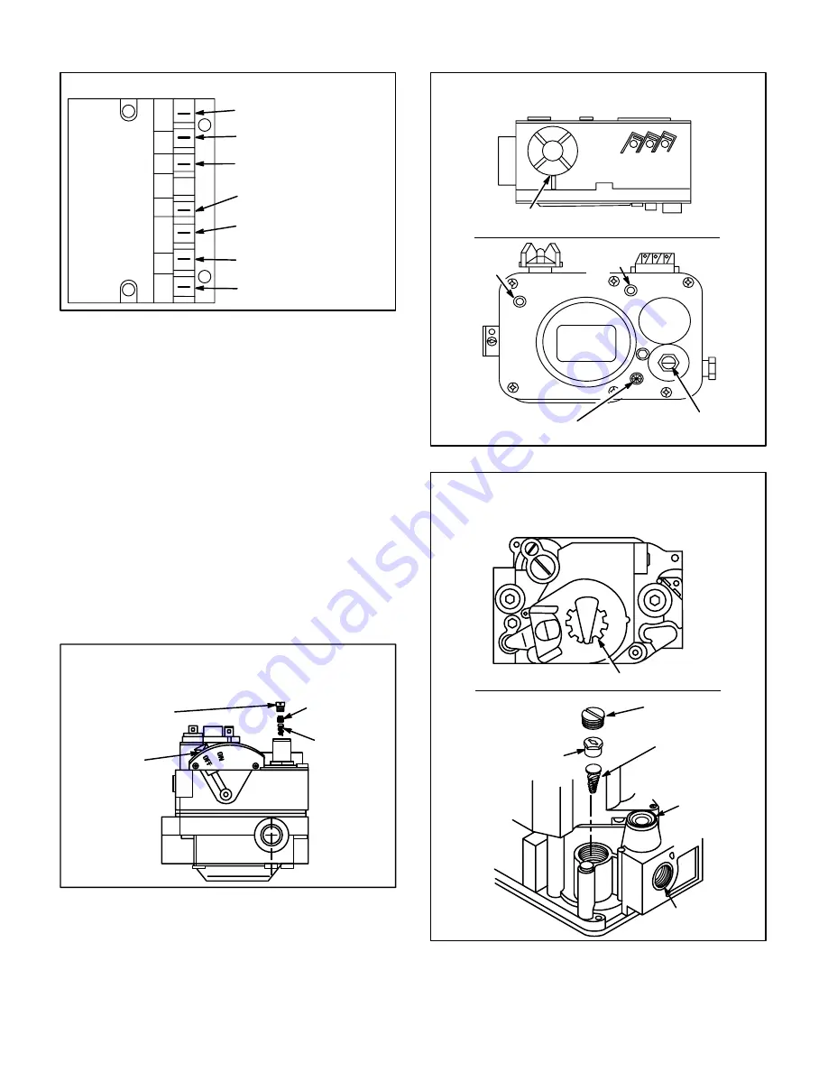
Inlet and outlet pressure taps are located on the valve. A
pilot adjusting screw and regulator adjustment screw (figĆ
ures 7 and 9) are located on the valve. Refer to figure 8 for
exact location of valve features.
FIGURE 7
(Robertshaw 7200 gas valve shown)
GAS VALVE
SELECTOR
ARM
IN OFF
POSITION
REGULATOR
COVER SCREW
ADJUSTING
SCREW
SPRING
TYPICAL ACCESS TO REGULATOR
FOR ADJUSTMENT AND L.P. CHANGEOVER
An LPG changeover kit is available from Lennox. The kit inĆ
cludes main and pilot burner orifices, burner air adjustment
shutters and a regulating conversion kit.
ON
OFF
FIGURE 8
(Robertshaw 7100 gas valve shown)
GAS VALVE KNOB SHOWN IN
OFF POSITION
P C M
PRESSURE REGULATOR
ADJUSTMENT SCREW
TOP VIEW
FRONT
VIEW
PILOT
ADJUSTMENT SCREW
INLET
PRESSURE
TAP
VALVE
INLET
VALVE
OUTLET
OUTLET
PRESSURE
TAP
TYPICAL GAS VALVE COMPONENTS
FIGURE 9
TYPICAL ACCESS TO REGULATOR
FOR ADJUSTMENT AND L.P. CHANGEOVER
ON
OFF
(Honeywell VR8204 series gas valve shown)
GAS VALVE SHOWN IN OFF POSITION
INLET
PRESSURE
TAP
CAP SCREW
(Black)
ADJUSTING SCREW
(White)
SPRING
Tapered End
Down
(Red)
GAS INLET
PRESSURE
REGULATOR


