Page 16
11-Set thermostat to desired setting.
NOTE-When unit is initially started, steps 1 through 11
may need to be repeated to purge air from pilot line.
12-If the appliance still will not operate, follow the instrucĆ
tions To Turn Off Gas To Unit" and call your service
technician or gas supplier.
To Turn Off Gas To Unit
1- Set thermostat to lowest setting.
2- Turn off all electrical power to unit if service is to be perĆ
formed.
3- Remove lower access panel.
4- On Honeywell VR8204 gas valves, turn knob on gas
valve clockwise
to
OFF
. Units with Robertshaw 7200
gas valve, depress lever and move to
OFF
position. Do
not force.
5- Replace lower access panel.
HIGH ALTITUDE INFORMATION
G20R series units are certified for installations from 0 to
4000 feet (0 to 1219m) above sea level without modificaĆ
tion. For installations from 4000 feet to 7500 feet (1219m
to 2286m) above sea level, a high altitude kit (44H56)
must be installed. The kit contains special flue baffles
used to replace factory-installed baffles. No derate is reĆ
quired.
GAS PRESSURE ADJUSTMENT
Gas Flow
To check for proper gas flow to combustion chamber, deĆ
termine Btu input from appliance rating plate. Divide this
input rating by the Btu per cubic foot of available gas. ReĆ
sult is the required number of cubic ft. per hour. DeterĆ
mine the flow of gas through gas meter for two minutes
and multiply by 30 to get the hourly flow of gas to burner.
Gas Pressure
1- Check gas line pressure with unit firing at maximum
rate.
A minimum of 4.5" w.c. (1.12kPa) for natural
gas or 10.5" w.c. (2.61kPa) for LP/propane gas
should be maintained.
2-
After line pressure has been checked and adjusted,
check manifold pressure. Correct manifold presĆ
sure for LP/propane gas is 9.5" w.c. (2.36kPa) No adĆ
justment is needed in high altitude applications.
A natural gas to LP/propane gas changeover kit is
required to convert unit. Refer to the installation
instructions supplied with changeover kit for conĆ
version procedure.
Correct manifold pressure for natural gas is 3.5"
w.c. (.87kPa). No adjustment is needed in high altiĆ
tude applications.
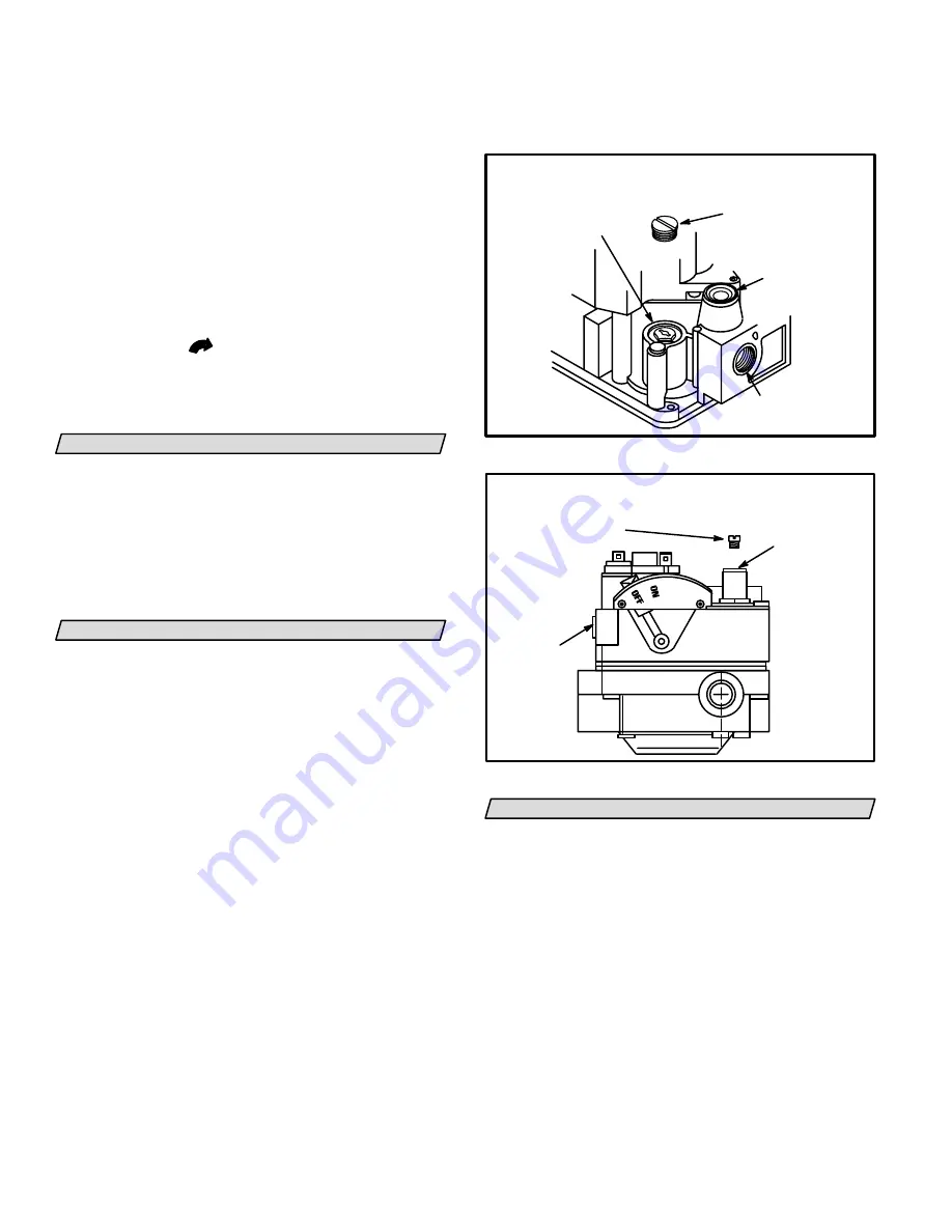
See figures 22 and 21 for gas
pressure adjustment screw location.
INLET
PRESSURE
TAP
HONEYWELL GAS VALVE
REGULATOR ADJUSTMENT SCREW LOCATION
CAP SCREW
(Black)
ADJUSTING SCREW
(White)
GAS INLET
PRESSURE REGULATOR
FIGURE 21
ROBERTSHAW 7200 GAS VALVE
REGULATOR ADJUSTMENT SCREW LOCATION
FIGURE 22
REGULATOR
COVER SCREW
ADJUSTING
SCREW
INLET
PRESSURE
TAP
OTHER UNIT ADJUSTMENTS
Limit Control
Limit Control-Factory set at 90 seconds: No adjustment
necessary. If nuisance tripping of limit control occurs, fan
may need to run longer. See Fan Control section below.
Fan Control
The fan on time of 45 seconds is not adjustable. Fan off
time (time that the blower operates after the heat deĆ
mand has been satisfied) can be adjusted by moving
the jumper on the BCC blower control center. The unit
is shipped with a factory fan off setting of 90 seconds.
Fan off time will affect comfort and is adjustable to satĆ
isfy individual applications. See figure 23.


