Page 6
K – Pilot Tube, Ignition Wire and Flame Rod
The pilot tube from the gas valve and the flame sensor
and ignition wires from the electronic ignition control
enter through the top of the burner box to the pilot
burner assembly.
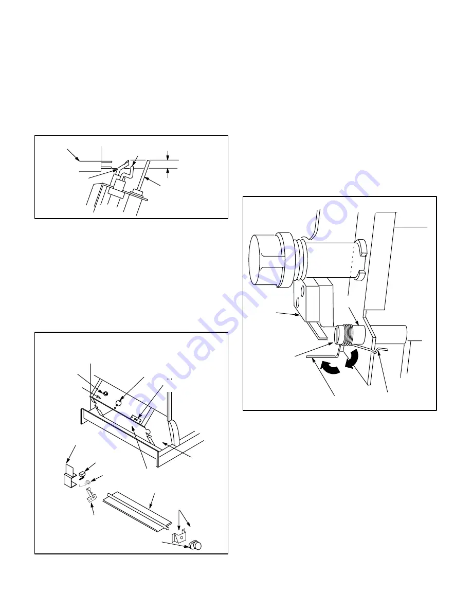
Figure 8 shows the clearance between top of the pilot
burner head and the top of the main burner surface.
IGNITION
WIRE
FLAME SENSOR
WIRE
PILOT ASSEMBLY
5/16”
PILOT
HEAD
FIGURE 8
BURNER
SURFACE
L – Burner Box/Damper Door
The damper motor is located on the right side of the
burner box. On the left side of the burner box, behind a
protective plate is the damper prove switch. Refer to
figure 9. The burner box top is removable on all units.
When there is a call for heat, the damper motor is ener-
gized and damper door opens as the damper motor
axle begins to rotate.
REMOVEABLE
TOP
DAMPER MOTOR/GEAR
PATCH PLATE
PATCH PLATE
SPRING
DAMPER
PROVE SWITCH
PROVE
SWITCH COVER
OBSERVATION PORT
COVER
DAMPER
PILOT PATCH
PLATE
DAMPER
BOX
DAMPER BOX PARTS ARRANGEMENT
(G20RE Units Shown)
DAMPER OPENING
FIGURE 9
ROLL–OUT
SWITCH
M – Damper Prove Switch (S64)
The spring, which is held by a notch in the burner box
frame, activates the damper prove switch as the damp-
er door opens. See figure 10. The axle rotates the
damper door to open position. As the axle turns, the
spring winds backward to make contact with the damp-
er prove switch. The protective cover plate is remov-
able (one screw) and the spring may be unclipped for
service to the damper door or burner box. Spring must
be removed in order to remove the damper door.
After service is complete, the spring must rest snugly
in notch for damper prove switch to function properly.
Do not force door open, damage to the spring and mo-
tor may occur. Take care to open damper door slowly.
Axle rotates
and opens the
door, slot in left
end of axle
pulls spring
back to activate
damper prove
switch.
DAMPER
PROVE
SWITCH
SPRING
SPRING FITS
SNUGLY IN NOTCH
FIGURE 10
AXLE
DAMPER
DOOR
DAMPER PROVE SWITCH ASSEMBLY
MANIFOLD
III – PLACEMENT AND INSTALLATION
Make sure the unit is installed in accordance with
installation instructions and all applicable codes.
IV – START-UP
A – Preliminary and Seasonal Checks
1 – Inspect electrical wiring, both field and factory
installed for loose connections. Tighten as re-
quired.
2 – Check voltage at disconnect switch. Voltage must
be within range listed on the nameplate. If not, con-
sult the power company and have voltage condi-
tion corrected before starting unit.


