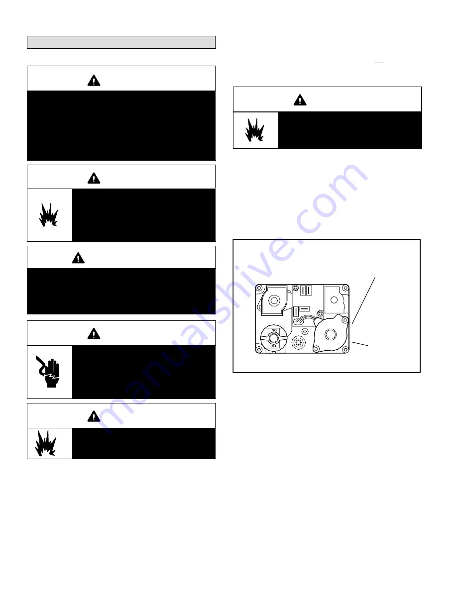
Page 33
Unit Start−Up
FOR YOUR SAFETY READ BEFORE LIGHTING
WARNING
Do not use this furnace if any part has been under
water. A flood−damaged furnace is extremely dan-
gerous. Attempts to use the furnace can result in
fire or explosion. A qualified service agency
should be contacted to inspect the furnace and to
replace all gas controls, control system parts, elec-
trical parts that have been wet or the furnace if
deemed necessary.
WARNING
Danger of explosion. Can cause injury
or product or property damage. Should
the gas supply fail to shut off or if
overheating occurs, shut off the gas
valve to the furnace before shutting off
the electrical supply.
WARNING
SMOKE POTENTIAL
The heat exchanger in this unit could be a source of
smoke on initial firing. Take precautions with respect
to building occupants and property. Vent initial sup-
ply air outside when possible.
WARNING
Electric shock hazard. Can cause
injury or death. Before attempting to
perform any service or maintenance,
turn the electrical power to unit OFF at
disconnect switch(es). Unit may have
multiple power supplies.
WARNING
Danger of explosion. Can cause injury or
death. Do not attempt to light manually.
Unit has a direct spark ignition system.
BEFORE LIGHTING
smell all around the appliance area for
gas. Be sure to smell next to the floor because some gas is
heavier than air and will settle on the floor.
Use only your hand to push in or turn the gas control knob.
Never use tools. If the knob will not push in or turn by hand,
do not try to repair it, call a qualified service technician.
Force or attempted repair may result in a fire or explosion.
Placing Furnace Into Operation
G24−200 units are equipped with two direct spark ignition
systems − one for each heat section. Do not attempt to
manually light burners on these furnaces. Each time ther-
mostat calls for heat, the burners will automatically light.
WARNING
Danger of explosion and fire. Can cause
injury or product or property damage.
You must follow these instructions
exactly.
Gas Valve Operation − White Rodgers 36E Two-Stage
Gas Valve (Figure 20)
1 − Set the thermostat to the lowest setting.
2 − Turn off all electrical power to the unit.
3 − This furnace is equipped with an ignition device
which automatically lights the burners. Do
not
try to
light the burners by hand.
4 − Remove the control access panels.
WHITE RODGERS 36E GAS VALVE
GAS VALVE KNOB SHOWN IN OFF" POSITION
LOW HEAT MANIFOLD
PRESSURE FACTORY-SET,
NOT FIELD-ADJUSTABLE.
MANIFOLD
PRESSURE
OUTLET ON SIDE.
HIGH HEAT MANIFOLD
PRESSURE ADJUSTMENT
FIGURE 20
5 − Perform the following to
both
gas valves − Turn knob
on gas valve 180
either way to
OFF.
Do not force.
6 − Wait five minutes to clear out any gas. If you then
smell gas,
STOP!
Immediately call your gas supplier
from your neighbor’s phone. Follow the gas supplier’s
instructions. If you don’t smell gas go to next step.
7 − Perform the following to
both
gas valves − Turn knob
on gas valve 180
either way to
ON
position.
8 − Replace the control access panels.
9 − Turn on all electrical power to the unit.
10 −Set the thermostat to desired setting.
11 −Both combustion air blowers will start. The burners
in both heat sections will light after a 45-second pre-
purge.


