Page 12
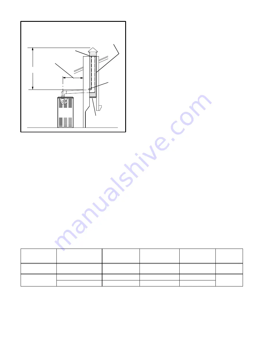
VENTING USING METAL-LINED
EXTERIOR MASONRY CHIMNEY
1.5m (5 FT.)
MINIMUM
SEALED
PERMANENTLY SEALED
FIREPLACE OPENING
EXTERIOR CHIMNEY WITH TWIN-WALLED LINER OR
INSULATED (FLEXIBLE) SINGLE-WALLED LINER.
Note: See the regulations that are in force in the
country of installation for flue connector sizing.
MIN. LENGTH - AS SHORT AS PRACTICAL
MAXIMUM LENGTH - SEE NOTE AT SIDE
HIGHEST FLUE
CONNECTOR POINT
FIGURE 15
Do not install a manual damper, barometric draught reguĆ
lator, or flue restrictor between the furnace and the chimĆ
ney. Remove any such existing devices.
If twin-wall flue is used inside a chimney, no other apĆ
pliance can be vented into the chimney. Outer wall of twin-
wall flue pipe must not be exposed to flue products.
If a flexible single-walled liner is used in a masonry chimĆ
ney, the liner must be insulated. Insulation for the flexible
vent pipe must be an encapsulated fiberglass sleeve recĆ
ommended by the flexible vent pipe manufacturer. See
figure 15.
If twin-wall flue or an insulated flexible vent pipe cannot be
used as liners, the chimney must be rebuilt to accommoĆ
date one of these methods or some alternate approved
method must be found to vent the appliance.
The space between the liner and the chimney wall
should NOT be insulated with puffed mica or any othĆ
er loose granular insulating material.
When inspection reveals that an existing chimney is not
safe for the intended purpose, it shall be rebuilt to conform
to nationally recognized standards. The chimney pasĆ
sageway must be checked periodically to ensure that it is
clear and free of obstructions.
HORIZONTAL FLUE USING METAL FLUE PIPE
These instructions should be used as a guide and do not
supersede local codes in any way. Size and install the
G24MCE horizontal flue according to the national and loĆ
cal codes and regulations which are in effect in the counĆ
try of installation.
The following are specific requirements for installation of
the G24MCE furnace:
1 - Install first flue connector elbow a minimum of
152mm (6 in.) from the furnace flue outlet.
2 - If the flue is sloped upward as it is routed away from
the furnace, the furnace must be protected from the
condensate produced in the flue.
3 - The flue system must be sealed (all joints must be
sealed), as positive pressure can occur in the flue.
4 - A 152mm (6 in.) clearance must be maintained to all
combustibles when single-walled flue pipe is used. A
25mm (1 in.) clearance to all combustibles must be
maintained when twin-walled flue pipe is used.
5 - If single-walled flue is used, fasten the flue adapter
to the flue outlet of the furnace and the flue connector
to the flue adapter using one or two corrosion-resisĆ
tant sheet metal screws. If twin-walled flue pipe is
used, fasten to the adapter according to manufacturĆ
er's instructions.
6 - Support flue as required by the regulations in force.
7 - See table 3 for flue diameter, equivalent lengths and
termination allowed.
8 - The tee termination shown in figures 16 and 17 is the
only acceptable termination.
TABLE 3
HORIZONTAL FLUE PIPE SIZING
MODEL SIZE
UNIT ORIENTATION
MINIMUM FLUE PIPE
DIAMETER mm (in.)
MINIMUM FLUE
EQUIVALENT
LENGTH* m (ft.)
MAXIMUM FLUE
EQUIVALENT
LENGTH* m (ft.)
TERMINATION
TEE
45
HORIZONTAL
UPFLOW / DOWNFLOW
102 (4)
3 (10)
9.2 (30)
1
HORIZONTAL
102 (4)
3 (10)
9.2 (30)
60/75/100/120/140
UPFLOW / DOWNFLOW
102 (4)
3 (10)
13.7 (45)
1
*One 90
5
elbow equals 1.5 m (5 ft.) of straight pipe. One 45
5
elbow equals 0.75 m (2.5 ft.) of straight pipe.


![Roberts Gorden Combat UHD[S] 150-400 Specifications preview](http://thumbs.mh-extra.com/thumbs/roberts-gorden/combat-uhd-s-150-400/combat-uhd-s-150-400_specifications_1469644-1.webp)


