Page 8
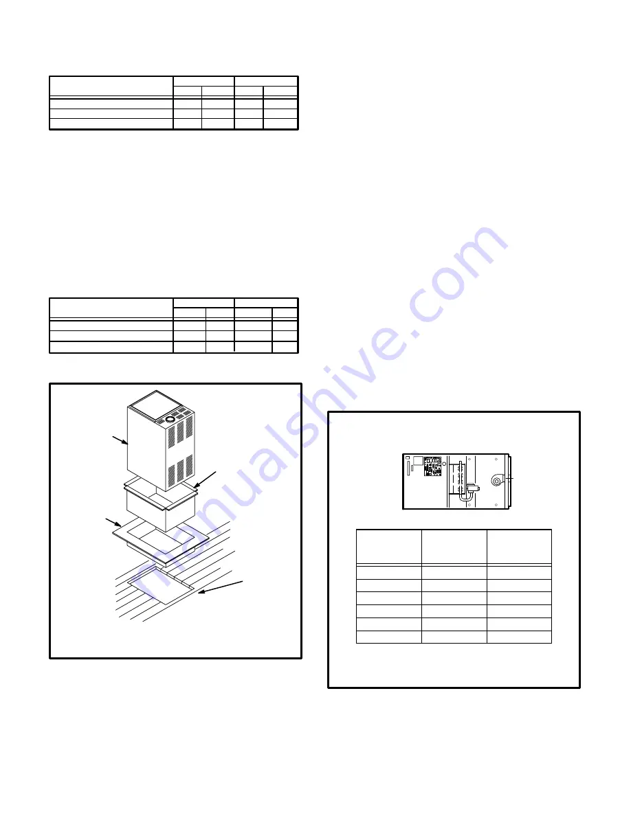
TABLE 1
NONCOMBUSTIBLE FLOOR OPENING
UNIT
Front to Rear
Side to Side
in
mm
in
mm
G24MCE-45/60/75
502
388
NOTE-Floor opening dimensions listed are 6mm (1/4") larger
than unit openings.
19-3/4
15-1/4
G24MCE-100/120
502
477
19-3/4
18-3/4
G24MCE-140
502
546
19-3/4
21-1/2
2 - Flange warm air plenum and lower into opening.
3 - Set unit over plenum.
4 - Check to see that an adequate seal is made.
B-Installation on Combustible Flooring
1 - When unit is installed on a combustible floor, an addiĆ
tive base (ordered separately) must be installed beĆ
tween the furnace and the floor. See table 2 for openĆ
ing size to cut in the floor.
TABLE 2
ADDITIVE BASE FLOOR OPENING
UNIT
Front to Rear
Side to Side
in
mm
in
mm
G24MCE-45/60/75
556
440
NOTE-Floor opening dimensions listed are 1/4" (6mm) larger
than additive base openings.
21-7/8
17-5/16
G24MCE-100/120
556
528
21-7/8
20-3/4
G24MCE-140
556
597
21-7/8
23-1/2
G24MCE UNIT
SUPPLY AIR
PLENUM
ADDITIVE
BASE
PROPERLY
SIZED FLOOR
OPENING
1. Cut correct size floor opening
2. Set additive base into opening.
3. Set supply air plenum into additive base.
4. Set unit.
FIGURE 8
2 - After opening is cut, set the additive base into
opening.
3 - Check glass fibre strips on additive base to make
sure they are properly glued and positioned.
4 - Lower supply air plenum into additive base until pleĆ
num flanges seal against glass fibre strips.
5 - Set unit on additive base so unit flanges drop into pleĆ
num. Refer to figure 8.
NOTE-Be careful not to damage glass fibre strips.
Check for tight seal.
C-Installation on Cooling Cabinet
1 - Refer to reverse flow coil installation instructions for
correctly sized opening in floor and installation of
cabinet.
2 - When cooling cabinet is in place, install furnace so
flanges drop inside cabinet opening.
3 - Seal cabinet and check for air leakage.
HORIZONTAL APPLICATIONS
The Lennox G24MCE furnace can be installed in horizonĆ
tal applications in either upflow or downflow configuration
(See figure 6). It is preferable to install the unit in the stanĆ
dard upflow configuration, if possible, because the vent
pipe will not interfere with service access for fan.
The unit
cannot be installed on its back.
Filter rack is provided. Adjustable rack can be installed
flush with cabinet edges.
Allow for clearances to combustible materials as indicated
on the unit rating plate. Minimum clearances for cupboard
or alcove installations are shown in
figure 9.
HORIZONTAL APPLICATION
INSTALLATION CLEARANCES
VENT
CONNECTOR
TYPE
SINGLE WALL
TWIN WALL
TOP
25mm (1 in.)
25mm (1 in.)
*FRONT
51mm (2 in.)
51mm (2 in.)
BACK
SIDES
FLUE
152mm (6 in.)
BOTTOM
TOP
RIGHT
SIDE
LEFT
SIDE
*Front clearance in alcove installation must be a miniĆ
mum of 610mm (24 in.) for service access.
**On combustible floor with non-combustible protection.
NC - Non-Combustibles
BOTTOM
**NC
**NC
25mm (1 in.)
25mm (1 in.)
51mm (2 in.)
51mm (2 in.)
25mm (1 in.)
FIGURE 9


