Page 17
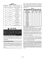
TABLE 6
GAS PIPE CAPACITY - ft.
3
/hr (m
3
/hr)
Nominal
Internal
Length of Pipe-Feet (m)
Nominal
Iron Pipe Size
-Inches(mm)
Internal
Diameter
-Inches(mm)
10
(3.048)
20
(6.096)
30
(9.144)
40
(12.192)
50
(15.240)
60
(18.288)
70
(21.336)
80
(24.384)
90
(27.432)
100
(30.480)
1/4
(6.35)
.364
(9.246)
43
(1.13)
29
(.82)
24
(.68)
20
(.57)
18
(.51)
16
(.45)
15
(.42)
14
(.40)
13
(.37)
12
(.34)
3/8
(9.53)
.493
(12.522)
95
(2.69)
65
(1.84)
52
(1.47)
45
(1.27)
40
(1.13)
36
(1.02)
33
(.73)
31
(.88)
29
(.82)
27
(.76)
1/2
(12.7)
.622
(17.799)
175
(4.96)
120
(3.40)
97
(2.75)
82
(2.32)
73
(2.07)
66
(1.87)
61
(1.73)
57
(1.61)
53
(1.50)
50
(1.42)
3/4
(19.05)
.824
(20.930)
360
(10.19)
250
(7.08)
200
(5.66)
170
(4.81)
151
(4.28)
138
(3.91)
125
(3.54)
118
(3.34)
110
(3.11)
103
(2.92)
1
(25.4)
1.049
(26.645)
680
(19.25)
465
(13.17)
375
(10.62)
320
(9.06)
285
(8.07)
260
(7.36)
240
(6.80)
220
(6.23)
205
(5.80)
195
(5.52)
1-1/4
(31.75)
1.380
(35.052)
1400
(39.64)
950
(26.90)
770
(21.80)
660
(18.69)
580
(16.42)
530
(15.01)
490
(13.87)
460
(13.03)
430
(12.18)
400
(11.33)
1-1/2
(38.1)
1.610
(40.894)
2100
(59.46)
460
(41.34)
1180
(33.41)
990
(28.03)
900
(25.48)
810
(22.94)
750
(21.24)
690
(19.54)
650
(18.41)
620
(17.56)
2
(50.8)
2.067
(52.502)
3950
(111.85)
2750
(77.87)
2200
(62.30)
1900
(53.80)
1680
(47.57)
1520
(43.04)
1400
(39.64)
1300
(36.81)
1220
(34.55)
1150
(32.56)
2-1/2
(63.5)
2.469
(67.713)
6300
(178.39)
4350
(123.17)
3520
(99.67)
3000
(84.95)
2650
(75.04)
2400
(67.96)
2250
(63.71)
2050
(58.05)
1950
(55.22)
1850
(52.38)
3
(76.2)
3.068
(77.927)
11000
(311.48)
7700
(218.03)
6250
(176.98)
5300
(150.07)
4750
(134.50)
4300
(121.76)
3900
(110.43)
3700
(104.77)
3450
(97.69)
3250
(92.03)
4
(101.6)
4.026
(102.260)
23000
(651.27)
15800
(447.39)
12800
(362.44)
10900
(308.64)
9700
(274.67)
8800
(249.18)
8100
(229.36)
7500
(212.37)
7200
(203.88)
6700
(189.72)
NOTE - Capacity given in cubic feet (
m
3
) of gas per hour and based on 0.60 specific gravity gas.
Electrical
A field make-up box is provided for line voltage wiring.
Line voltage wiring to unit is done through the J69 jack
from the field make-up box to plug P69 from the control
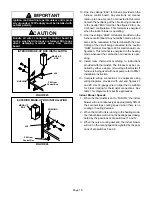
box. See figures 25 and 26 for make-up box installation.
Refer to figure 27 for schematic wiring diagram and trouĆ
bleshooting, figure 28 for point-to-point field wiring and
figure 29 for a detailed illustration of the Surelight inteĆ
grated control.
ELECTROSTATIC DISCHARGE (ESD)
Precautions and Procedures
CAUTION
Electrostatic discharge can affect electronic comĆ
ponents. Take precautions during furnace installaĆ
tion and service to protect the furnace's electronic
controls. Precautions will help to avoid control exĆ
posure to electrostatic discharge by putting the
furnace, the control and the technician at the same
electrostatic potential. Neutralize electrostatic
charge by touching hand and all tools on an unĆ
painted unit surface, such as the gas valve or blowĆ
er deck, before performing any service procedure.
1 - Select circuit protection and wire size according to
the unit nameplate. The power supply wiring must
meet Class 1 restrictions.
2 - A snaphole bushing is provided to seal around the
wiring as it enters the cabinet. A snaphole plug is proĆ
vided to seal the unused wire entry hole.
3 - Install a separate disconnect switch (protected by eiĆ
ther a fuse or circuit breaker) near the unit so that
power can be turned off for servicing.
4 - Install field makeĆup box on either side, inside or out
of the cabinet. Knockouts are provided in box and
cabinet to facilitate wiring. See figures 25 and 26.
To ensure proper grounding of the furnace, two lockĆ
washers are included in the electrical make-up box
bag assembly. Place each lockwasher on a securing
screw before installing the make-up box. Make sure
the lockwasher breaks the paint on the cabinet so
that the washer is touching metal. Unit is not properly
grounded if paint has not been removed by the lockĆ
washer.
5 - Remove cap from knockout in blower deck on the
same side as the installed make-up box.
6 - Insert the three-pin (P69) plug from the control box
into the knockout provided in the blower deck.
7 - Connect jack (J69) from make-up box to jack plug in
blower deck.
8 - Before connecting the thermostat or the power wirĆ
ing, check to make sure the wires will be long enough
for servicing at a later date. Remove the blower acĆ
cess panel to check the length of the wire.
9 - Electrically ground unit in accordance with local
codes or, in the absence of local codes, according to
the current National Electric Code (ANSI/NFPA No.
70) and in Canada with the current Canadian Electric
Code part 1 (CSA standard C22.1). The ground wire
is provided in the field make-up box.


