Page 18
IMPORTANT
Ignition control will not operate unless unit is propĆ
erly grounded. 120V supply must be installed with
correct polarity.
CAUTION
Bundle all wires connected to control board in
such a way that drip loops are formed. Drip loops
direct damaging moisture away from control
board.
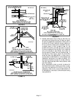
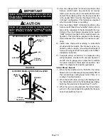
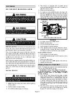
INTERIOR MAKE-UP BOX INSTALLATION
P69 from
Control Box
J69
MAKE-UP
BOX
BUSHING
FIGURE 25
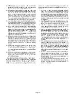
FIGURE 26
EXTERIOR MAKEĆUP BOX INSTALLATION
P69 from
Control Box
J69
MAKE-UP
BOX
BUSHING
10 -One line voltage EAC" terminal is provided on the
furnace control board. Any electronic air cleaner
rated up to one amp can be connected to this termiĆ
nal with the neutral leg of the circuit being connected
to the neutral EAC" terminal. See figure 29 for conĆ
trol board configuration. This terminal is energized
when the indoor blower is operating.
11 -One line voltage HUM" terminal is provided on the
furnace control board. Any humidifier rated up to one
amp can be connected to this terminal with the neuĆ
tral leg of the circuit being connected to the neutral
HUM" terminal. See figure 29 for control board conĆ
figuration. This terminal is energized in the heating
mode whenever the combustion air inducer is operĆ
ating.
12 - Install room thermostat according to instructions
provided with thermostat. The furnace may be conĆ
trolled by either a single- or two-stage thermostat. If
furnace is being used with heat pump refer to FM21
installation instruction.
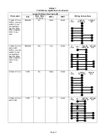
13 - Complete wiring connections to equipment using
wiring diagrams provided with unit and figures 27
and 28. Use 18-gauge wire or larger that is suitable
for Class II rating for thermostat connections. See
table 7 for diagrams for specific applications.
Indoor Blower Speeds
1 - When the thermostat is set to FAN ON," the indoor
blower will run continuously at approximately 38% of
the second-stage cooling speed when there is no
cooling or heating demand.
2 - When the G32V unit is running in the heating mode,
the indoor blower will run on the heating speed desigĆ
nated by the positions of dip switches 11 and 12.
3 - When there is a cooling demand, the indoor blower
will run on the cooling speed designated by the posiĆ
tions of dip switches 5 and 6.

