background image

Page 29

Electronic Ignition

The SureLight

®

 integrated control has an added feature of

an internal Watchguard control. The feature serves as an
automatic reset device for ignition control lockout caused
by ignition failure. After one hour of continuous thermostat
demand for heat, the Watchguard will break and remake
thermostat demand to the furnace and automatically reset
the control to begin the ignition sequence.

Flue And Chimney

 1 − Check flue pipe, chimney and all connections for tight-

ness and to make sure there is no blockage.

 2 − Check unit for proper draft.
 3 − Is pressure switch closed? Obstructed flue will cause

unit to shut off at pressure switch. Check flue and outlet
for blockages.

 4 − Reset manual flame rollout switches on burner box

cover.

Failure To Operate

If the unit fails to operate, check the following:

 1 − Is the thermostat calling for heat?
 2 − Are access panels securely in place?
 3 − Is the main disconnect switch closed?
 4 − Is there a blown fuse?
 5 − Is the filter dirty or plugged? Dirty or plugged filters will

cause the limit control to shut the unit off.

 6 − Is gas turned on at the meter?
 7 − Is the manual main shut-off valve open?
 8 − Is the internal manual shut-off valve open?
 9 − Is the unit ignition system in lock out? If the unit locks out

again, inspect the unit for blockages.

Service

WARNING

Disconnect power before servicing unit.

CAUTION

Label all wires prior to disconnection when servicing
controls. Wiring errors can cause improper and dan-
gerous operation. Verify proper operation after ser-
vicing.

At the beginning of each heating season, a qualified techni-
cian should check the system as follows:

Blower

Check the blower wheel for debris and clean if necessary.
The blower motors are prelubricated for extended bearing
life. No further lubrication is needed.

WARNING

The blower access panel must be securely in place
when the blower and burners are operating. Gas
fumes, which could contain carbon monoxide, can
be drawn into living space resulting in personal inju-
ry or death.

Filters

All G50DF(X) filters are installed external to the unit. Filters
should be inspected monthly. Clean or replace the filters
when necessary to ensure that the furnace operates prop-
erly. Replacement filters must be rated for high velocity air-
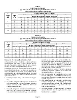
flow. Table 3 lists recommended filter sizes.

Flue And Chimney

Check the flue pipe, chimney and all connections for tight-
ness and to make sure there is no blockage.

Electrical

 1 − Check all wiring for loose connections.
 2 − Check for the correct voltage at the furnace (furnace

operating).

 3 − Check amp−draw on the blower motor.

Motor Nameplate__________Actual__________

Cleaning the Heat Exchanger and Burners

NOTE − Use papers or protective covering in front of the fur-
nace during cleaning.

Cleaning the heat exchanger requires a steel spring
snake," a reversible drill and a vacuum cleaner. The steel
spring snake may be constructed using a 4 ft. long by 1/4
inch diameter steel wire cable and a 1/4 inch diameter wire
brush. These items are available at a hardware store. In-
sert wire end of brush into the open end of the spring cable.
Crimp the cable around the brush so that the brush is se-
cured and will not come off during cleaning. Attach the oth-
er end of the cable to the reversible drill to complete the tool
for cleaning the heat exchanger.

 1 − Turn off both electrical and gas supplies to the furnace.

Remove the furnace access panels.

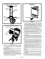
 2 − Remove the three screws that secure the vent pipe to

the flue collar. See figure 10.

 3 − Remove the screw that secures the internal flue pipe to

the combustion air inducer. See figure 25.

 4 − Scrape away the silicone sealant that is between the

internal flue pipe and the combustion air inducer.

 5 − Pull the internal flue pipe into the chase.
 6 − Label and disconnect the pressure switch wires.
 7 − Remove the four screws that secure the combustion

air inducer. Carefully remove the combustion air induc-
er to avoid damaging the blower gasket. If the gasket is
damaged, it must be replaced to prevent leakage. See
figure 26.

Summary of Contents for G50DF(X)?24A?045

Page 1: ...formance 27 Service 28 Repair Parts List 30 Planned Service 30 SureLight Integrated Control Diagnostic Codes 31 SureLight Control Troubleshooting 32 G50DF X Start Up Performance Check List 35 WHAT TO...

Page 2: ...4 7 8 124 Right 2 1 4 57 Left 40 1016 3 3 4 95 5 8 16 AIR FLOW 5 8 16 3 4 19 19 1 2 495 5 8 16 B 5 8 16 5 8 16 Supply Air Supply Air Model No A B C D in mm in mm in mm in mm G50DF X 24A 045 G50DF X 36...

Page 3: ...Flue Collector Box Gasket Combustion Air Inducer Gasket Manifold Burner Gas Valve Flame Rollout Switches Flame Sensor Primary Limit Ignitor Heat Exchanger Ignitor Bracket Combustion Air Pressure Swit...

Page 4: ...cal plumbing or waste water codes and other applicable local codes Adequate clearance must be made around the air open ings into the vestibule area In order to ensure proper unit operation combustion...

Page 5: ...alled in the system and must be maintained during construction D Air filters must be replaced upon construction comple tion D The input rate and temperature rise must be set per the furnace rating pla...

Page 6: ...ents as well as all local codes CAUTION Insufficient combustion air can cause headaches nausea dizziness or asphyxiation It will also cause excess water in the heat exchanger resulting in rust ing and...

Page 7: ...have a minimum free area of 1 square inch 645 mm2 per 1 000 Btu 29 kW per hour of total input rating of all gas fired equipment in the confined space Each opening must be at least 100 square inches 64...

Page 8: ...e square inch 645 mm2 per 4 000 Btu 1 17 kW per hour of the total input rating of all equip ment in the enclosure CHIMNEY OR GAS VENT WATER HEATER OUTLET AIR VENTILATION LOUVERS Each end of attic INLE...

Page 9: ...et 24 5 11M62 See table 2 for opening size to cut in floor CAUTION The furnace and additive base shall not be installed directly on carpeting tile or other combustible ma terial other than wood floori...

Page 10: ...it front The unit must be level NOTE 1 3 hp blower motors are equipped with four flex ible mounting legs and 1 2 hp blower motors are equipped with three flexible legs and one rigid leg The rigid leg...

Page 11: ...r any other gas fueled ap pliance i e water heater or carbon monoxide producing device i e wood fireplace is installed When return air is drawn from a room a negative pres sure is created in the room...

Page 12: ...If the existing chimney will not accommodate a B1 vent or an insulated flexible vent pipe liner either the chimney must be rebuilt to accommodate one of these liners or an alternate approved venting m...

Page 13: ...chimney passageway must be checked periodically to ensure that it is clear and free of obstructions Do not install a manual damper barometric draft regulator or flue restrictor between the furnace and...

Page 14: ...stened by screws or other approved means 12 When the vent connector used for Category I ap pliances must be located in or pass through a crawl space or other areas which may be cold that portion of th...

Page 15: ...22 339 5 22 65 30 130 39 219 49 330 10 29 59 40 121 51 206 64 315 15 35 53 48 112 61 195 76 301 20 0 0 97 0 202 0 349 0 540 2 10 75 14 149 18 250 20 377 5 21 71 29 143 38 242 47 367 10 28 64 38 133 50...

Page 16: ...225 115 337 5 51 63 75 128 102 216 144 326 10 NR NR 95 116 128 201 182 308 15 NR NR NR NR 158 186 220 290 20 0 35 96 54 200 78 346 114 537 2 37 74 56 148 78 248 113 375 5 50 68 73 140 100 239 141 363...

Page 17: ...1 21 50 33 89 47 142 64 220 2 22 53 35 96 49 153 66 235 3 24 55 36 102 51 163 68 248 20 1 21 54 33 99 46 157 62 246 2 22 57 34 105 48 167 64 259 3 23 60 35 110 50 176 66 271 30 1 20 62 31 113 45 181...

Page 18: ...rat ing and the other appliances which are not operating re main connected to the common venting system If the venting system has been installed improperly you must correct the system as indicated in...

Page 19: ...ng must be resistant to the actions of liquified petro leum gases NOTE Install a 1 8 inch NPT plugged tap in the field piping upstream of the gas supply connection to the unit The tap must be accessib...

Page 20: ...sting pressure of gas lines gas valve must be disconnected and isolated See figure 15 Gas valves can be damaged if subjected to pressures greater than 1 2 psig 3 48 kPa 14 inches w c MANUAL MAIN SHUT...

Page 21: ...rated up to one amp can be connected to this terminal with the neutral leg of the circuit being connected to any of the NEUTRAL terminals See figure 20 for control board configuration This terminal is...

Page 22: ...V HUM Blower Cooling Speed 120VAC Blower Heating Speed 120VAC Unused Blower Not energized Continuous Low Blower Speed Accessory Terminal 120VAC Transformer 120VAC Input 120VAC Heat Only Accessory 120V...

Page 23: ...Page 23 G50DF X Schematic Wiring Diagram FIGURE 21...

Page 24: ...is no call for heat on units with this ignition system WARNING If you do not follow these instructions exactly a fire or explosion may result causing property damage personal injury or death Gas Valve...

Page 25: ...is not detected after first ignition trial the igni tion control will repeat steps 3 and 4 four more times before locking out the gas valve WATCHGUARD flame failure mode The ignition control will then...

Page 26: ...fter supply and return air temperatures have stabilized check the temperature rise If necessary adjust the blower speed to maintain the temperature rise within the range shown on the unit nameplate In...

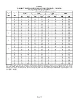
Page 27: ...70 390 855 338 720 280 0 80 960 434 875 359 735 299 665 266 0 90 770 389 715 321 665 278 590 244 G50DF 36B 090 PERFORMANCE External Static Pressure in w g Air Volume Watts at Different Blower Speeds H...

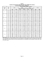
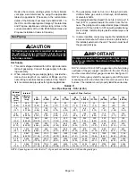
Page 28: ...um High Medium Low Low cfm Watts cfm Watts cfm Watts cfm Watts 00 2475 1276 2280 987 1995 845 1690 698 10 2390 1248 2235 955 1990 829 1675 690 20 2330 1223 2180 945 1975 809 1665 675 30 2245 1192 2125...

Page 29: ...could contain carbon monoxide can be drawn into living space resulting in personal inju ry or death Filters All G50DF X filters are installed external to the unit Filters should be inspected monthly...

Page 30: ...peat procedure for each heat exchanger section 14 After each of the top heat exchanger sections has been cleaned insert the brush end of the cable snake into the bottom openings of each of the heat ex...

Page 31: ...valve Main burner cluster Main burner orifices Pressure switch Ignitor Primary limit control Flame rollout switches Secondary limit Combustion Air Inducer Gaskets Flue Box Gaskets Flue Chase Gasket Se...

Page 32: ...ailed to ignite OR limit open more than 3 minutes OR lost flame sense 5 times in one heating cycle OR pressure switch opened 5 times in one heating cycle SLOW FLASH OFF Flame sensed without gas valve...

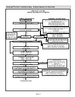
Page 33: ...NDUCER OFF INDOOR BLOWER OFF WITH DELAY LED 1 OFF LED 2 SLOW FLASH Sequence holds until pressure switch closes or thermostat resets control NO NO YES NO IS THERE PROPER GROUND IS VOLTAGE ABOVE 75 VOLT...

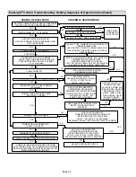
Page 34: ...UP 20 SECONDS YES 4 SECOND TRIAL FOR IGNITION GAS VALVE OPENS IGNITOR ENERGIZED FOR UP TO 4 SECONDS YES FLAME STABILIZATION PERIOD GAS VALVE OFF COMBUSTION AIR INDUCER ON INDOOR BLOWER OFF HAS CONTRO...

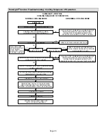
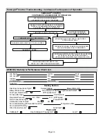
Page 35: ...T SWITCH CLOSED CHECK TO ENSURE GAS VALVE IS DE ENERGIZED IS GAS VALVE OFF LED SLOW FLASH RATE REMAINS UNCHANGED THROUGHOUT COOLING CYCLE THERMOSTAT CALLS FOR COOLING COMPRESSOR CONTACTOR IS ENERGIZED...

Page 36: ...OR BLOWER SWITCHES TO HEAT SPEED AFTER NORMAL DELAY INDOOR BLOWER SELECTED TIME OFF DELAY BEGINS AFTER DELAY HEAT SPEED DE ENERGIZED blower remains energized during continuous fan mode G50DF X Start U...

Reviews: