Page 22
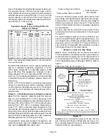
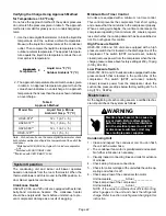
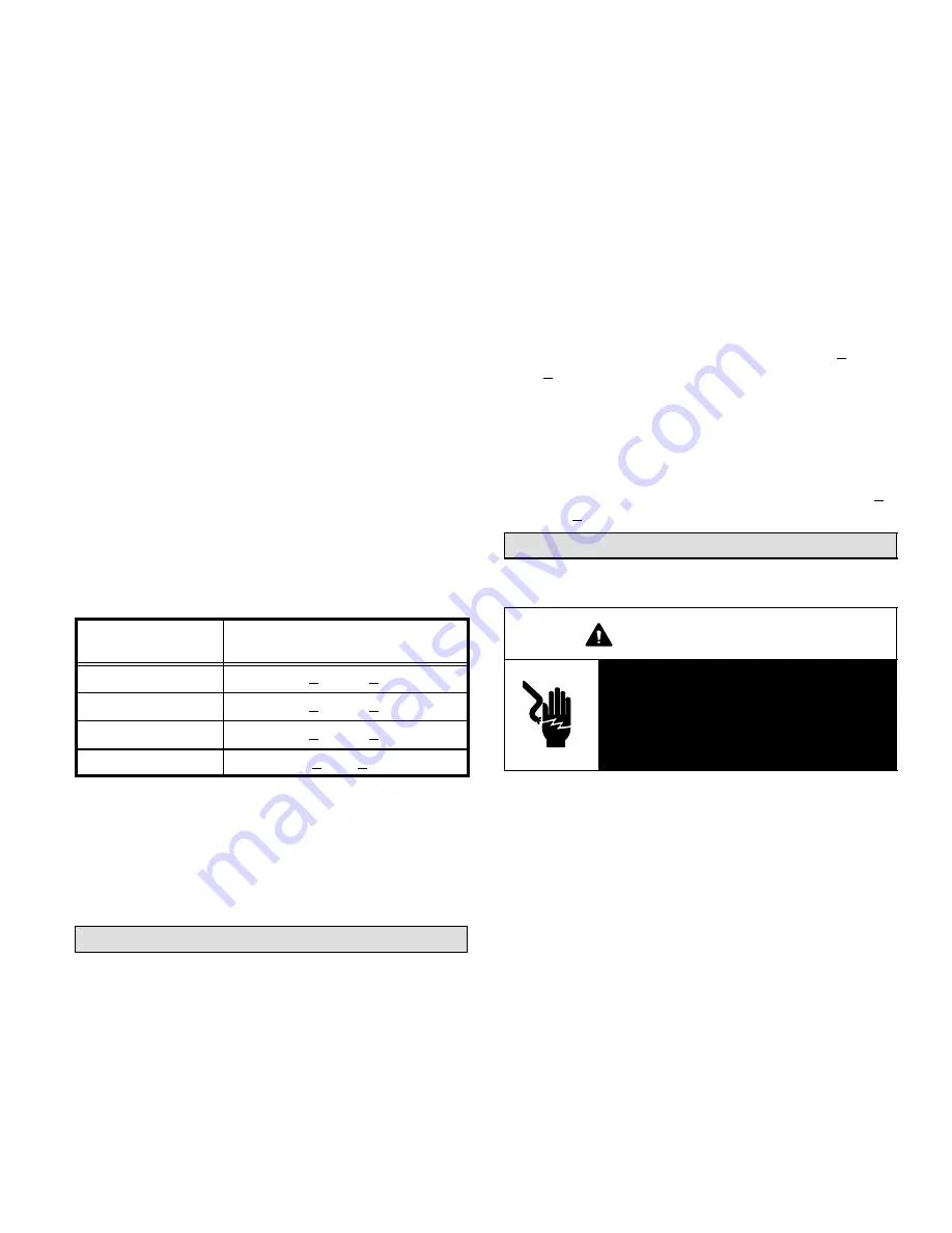
Verifying the Charge Using Approach Method
for Temperatures > 60°F only
Do not use the approach method if the system pressures
do not match the pressures given in table 5. The approach
method is not valid for grossly over or undercharged sys
tems.
1 − Use the same digital thermometer to take the liquid line
temperature and the outdoor ambient temperature.
Measure the liquid line temperature at the condenser
outlet. Then compare the liquid line temperature to the
outdoor ambient temperature. The approach tempera
ture equals the liquid line temperature minus the out
door ambient temperature:
Approach
=
−
Liquid Line °F (°C)
Approach
Temperature
=
−
Outdoor Ambient °F (°C)
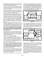
2 − The approach temperature should match values given
in table 6. An approach temperature greater than the
value shown indicates an undercharge. An approach
temperature that is less than the value shown indicates
an overcharge.
Table 6
Approach Method
Model No.
Liquid Temp. Minus
Ambient Temp. °F (°C)
HS29−072*
12 + 1 (6.7 + .5)
HS29−072**
16 + 1 (8.9 + .5)
HS29−090**
12 + 1 (6.7 + .5)
HS29−120***
9 + 1 (5 + .5)
Note − For best results, use the same digital thermometer check
both outdoor ambient and liquid line temperature at the exit of the
condenser.
*Matched with CB30U65 or typical 5ton indoor evaporator
coil.
**Matched with CB17/CBH17−95V.
***Matched with CB17/CBH17−135V.
System Operation
The condensing unit and indoor unit blower operates
based on demands from the room thermostat. When the
thermostat blower switch is moved to the
ON
position, in
door blower operates continuously.
Crankcase Heater
HS29−072, 090, and 120 units are equipped with external,
bellyband crankcase heaters. The crankcase heater
should be energized 24 hours before unit start−up to pre
vent compressor damage as a result of slugging.
Minimum Run Timer Control
All units are equipped with a minimum run time control.
This control prevents the compressor from short cycling
and ensures that the oil returns to the compressor properly.
When a cooling cycle begins, the run time control keeps the
compressor operating for a minimum of 4 minutes, regard
less of whether the cooling demand has been satisfied or
not. Do not bypass this control.
High Pressure Switch
HS29−072, 090 and 120 units are equipped with a high
pressure switch that is located in the discharge line of the
compressor. The switch (SPST, manual reset, normally
closed) removes power from the compressor when the dis
charge pressure rises above factory setting at 450+ 10 psig
(3103+ 69 kPa).
Low Pressure Switch
HS29−072, 090, and 120 units are also equipped with a low
pressure switch that is located in the suction line of the
compressor. The switch (SPST, auto−reset, normally
closed) removes power from the compressor when the
suction line pressure drops below factory setting at 25 + 5
psig (172 + 34 kPa).
Maintenance
At the beginning of each cooling season, a certified techni
cian should check the system as follows:
WARNING
Electric shock hazard. Can cause in
jury or death. Before attempting to
perform any service or maintenance,
turn the electrical power to unit OFF
at disconnect switch(es). Unit may
have multiple power supplies.
Condensing Unit
1 − Clean and inspect the condenser coil. You can flush
the coil with a water hose.
2 − The condenser fan motor is prelubricated and sealed.
No further lubrication is necessary.
3 − Visually inspect connecting lines and coils for evidence
of oil leaks.
4 − Check wiring for loose connections.
5 − Check for correct voltage at the unit while the unit is op
erating and while it is off.
6 − Check amp−draw of the condenser fan motor.
Unit nameplate _________ Actual ____________ .
Check amp−draw of the compressor.
Unit nameplate _________ Actual ____________ .
NOTE − If the owner complains of insufficient cooling,
attach gauges to the unit and check the refrigerant
charge. Refer to section on refrigerant charging in this
instruction.

