background image

507341-01

42

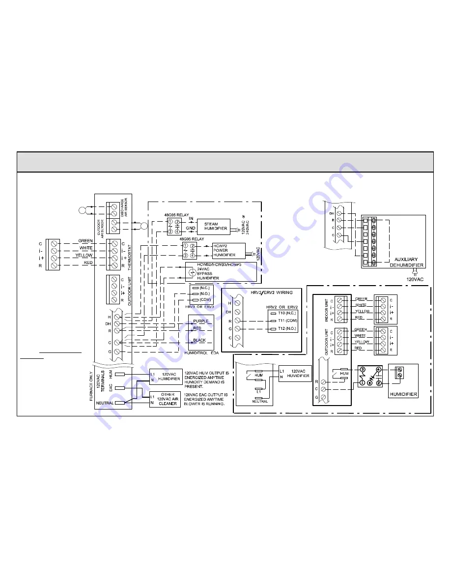
Optional Accessories Wiring
FOR USE WITH ANY ICOMFORT BY LENNOX

 SYSTEM

iComfort by Lennox

SLP98 & G71MPP FURNACE
(IFC) OR AIR HANDLER (AHC)

iComfort


Wi‐Fi

®

THERMOSTAT

DISCHARGE AIR SEN­
SOR (REQUIRED FOR
EVEN HEAT) (SEE DAS
NOTE ON PAGE 81)

NOTE: iComfort


Wi‐Fi

®

 THERMOSTAT SENSES HUMIDITY & CONTROLS 24V “H” OUTPUT (& 120V “H” OUTPUT)

TO CYCLE HUMIDIFIER BASED ON DEMAND. NO OTHER CONTROL OR HUMIDISTAT REQUIRED.

OPTIONAL OUTDOOR AIR SENSOR FOR USE WITH HUMIDIFIER (IF NOT ALREADY IN THE SYSTEM FOR OTHER
FUNCTIONS. BUILT INTO ALL iComfort by Lennox

 OUTDOOR UNITS). 

(SEE OAS NOTE ON PAGE 81)

Maximum total
length of all connec­
tions on the RSBus
is limited to 1500ft.

Wire gauge of
RSBus wire is 18.

Rf

W

Gh

Gs

Cf

HV
AC EQUIP

HCWH-01
DEHUMIDIFIER CONTROL

HVAC
EQUIPMENT

DH

NC

AUXILIARY DEHUMIDIFIER 090 & 135
capacities only (065 not compatible)

NOTE: 24V UV LIGHT
APPLICATIONS

In an iComfort by Lennox

system, neither furnace nor
air handler transformer will
have adequate VA to power
24V UV light applications.
An additional transformer for
UV light applications is re­
quired. UV light wiring con­
nections are independent of
HVAC system operation; see
UV light installation instruc­
tions.

iComfort by Lennox


SL280, EL296 FURNACE

48G96 Relay

GND

IN

iComfort

enabled 
outdoor unit

iComfort
Wi‐Fi

®

thermostat

RSBus

For SL290 & EL296, see HUMIDIFIER diagram
below (bottom right)

120VAC<-------

HUMIDIFIER CONNECTIONS

------> 24VAC

Summary of Contents for icomfort Wi-Fi

Page 1: ...r XP17N 01 or later XP25 01 or later CBX32MV 06 or later XP19 06 or later XC25 01 or later XC20 01 or later INSTALLER S SYSTEM SETUP GUIDE iComfort Wi Fi Thermostat TouchscreenProgrammable Communicating Thermostat CONTROLS 507341 01 8 2015 Supersedes 5 2015 Shipping and Packing List 1 iComfort Wi Fi thermostat firmware version 2 13 changes included 4 Mounting screws 4 Wall anchors 1 Homeowner s ma...

Page 2: ...nt alteration service or maintenance can cause property damage personal injury or loss of life Installationand service must be performed by a licensed professional HVAC installer or equivalent or service agency WARNING This is a 24VAC Class 2 thermostat Do not install on voltages higher than 30VAC Do not switch system to cool if the outdoor temperature is below 45 F 7 C This can damage the cooling...

Page 3: ...t Interface Module Catalog number 10T50 provides iComfort Wi FI to non communicating indoor unit Humidification measurement and control Dew point adjustment control Humiditrol Enhanced Dehumidification Accessory EDA Multiple stage HVAC systems Equipment maintenance reminders Autochangeover mode Permits control of heating cooling humidification and dehumidification without user involvement All Lenn...

Page 4: ...ically be populated once the thermostat has been registered during the Wi FI setup procedure later on in this instruction if the dealer has an account with Lennox already NOTE Dealer number is the dealer s Lennox account number Dealer phone number is the dealer s main office phone number 1 Use the arrows to scroll down to the Dealer Number or Dealer Phone setting Press the edit button 2 Enter the ...

Page 5: ...determining the location for the Wi Fi thermostat be sure it is in an area near enough to the home Wi Fi router to ensure good communications signal strength between the thermostat and the Wi Fi router Hint Use a smart phone with Wi Fi and Wi Fi finder application to locate and determine optimal location based on router Wi Fi signal strength NOTE Thermostat will not be able to reliably connect to ...

Page 6: ...the Wi FI network WI FI X NETWORK SETTINGS press to change network settings Must setup a network connection before registering thermostat connection status Press to see connection status Figure 6 Enable Wi FI Open connection which which requires no password Secure connection which requires Wi Fi password security key Add a network is required when Wi Fi identification SSID is being hidden not broa...

Page 7: ...twork press the add new network icon to continue Enter the network name SSID If security encryption is enabled then press the security is none icon Select either WEP WPA or WPA2 2 Using the on screen keyboard enter the password security key If the network name or security key combination is incorrect or incorrectly type and access to the specified network failed a message will alert you to retry 3...

Page 8: ...ccessible please contact your service provider for help The thermostat will connect to B G or N band routers at this time NOTE When set to B or G bands video streaming will likely be slower that N band If homeowner has implemented a dedicated N band router for the purpose of video streaming a separate router for the thermostat may be required 5 Reboot your router A Unplug your power cord wait 30 s...

Page 9: ...n the home make sure each router has a different name 17 If you don t get the pop up box that says the registration request has been forwarded then the email was not sent to the server and the return registration link will not be sent to your email address Try all the router troubleshooting procedures and if you still can t get it to send the email cycle the power to the thermostat This will cause...

Page 10: ...il address below is correct Verify the email address is correct and press yes 4 Another pop up screen will appear notifying the user to check their email An email has been sent to xxxxxxxxxx lennoxind com with instructions on how to register your thermostat If you haven t received the email please check your spam folder and make sure that your email address is correct NOTE If the email address ori...

Page 11: ...tton to toggle to OFF but is not recommended NOTE Firmware updates will not affect installer or user thermostat settings Both will be retained after the update WI FI SETTINGS connected Wi Fi enabled thermostat registered Connection to server has not bee established or it has been lost Please wait until a connection is established firmware update auto press to enable disable Wi Fi press to change w...

Page 12: ...om Auto to Off during a download will NOT stop the current download if it is already in process 4 Firmware Update Auto Default state If enabled the thermostat checks for firmware update a few minutes after commissioning and then every 24 hours in early morning hours 5 Once a download is completed the thermostat stops all activity for up to 3 seconds restarts for 5 seconds then continues with norma...

Page 13: ...er is installed the setting under the System mode Humidification Control Mode defaults to Basic Second if you want another mode i e Precision Basic Dew Point or Precision Dew Point the device requires further configuration see page 15 ADDING HUMIDITROL OR AN AUXILIARY DEHUMIDIFIER Before adding a dehumidifier be sure that the dehumidifier is wired to the furnace or air handler control as shown on ...

Page 14: ... 2 Humiditrol only In the System list use the arrows to highlight Humiditrol Comfort Adjust The current value defaults to Maximum Overcooling Touch edit 3 Humiditrol only Touch one of the radio buttons to select the overcooling level touch save After saving check that the current value now shows the new selection 4 Use arrows to highlight Min Dehumidification Setpoint touch edit Note the current v...

Page 15: ...o highlight Humidification Control Mode Touch edit 3 Touch one of the radio buttons to select the mode of humidification control touch save After saving check that the current value now shows the new selection 4 Touch the back button to return to Adjust a setting screen NOTE If the defaults for the settings are shown in red you are not required to make any changes but you must go into the edit too...

Page 16: ...miditrol Comfort Adjust The current value defaults to Maximum Overcooling Touch edit 3 Humiditrol only Touch one of the radio buttons to select the overcooling level touch save After saving check that the current value now shows the new selection 4 Use arrows to highlight Min Dehumidification Setpoint touch edit Note the current value e g 45 5 Use arrows to make changes touch After saving check th...

Page 17: ...one dehumidification thermo stat and a separate wire run to G terminal on indoor unit to start the blower Zoning Control Settings NOTE Skip if no zoning control device is installed A Heat Cool Changeover The following is an example of how the system operates during a heating cooling changeover When the system is satisfying a call from zone 1 for heating and receives a call for cooling from zone 2 ...

Page 18: ...irflow or Heating Airflow 2 Adjust airflow for a specific zone by pressing on the desired zone Total maximum airflow for all zones in this example is a combined1250 CFM Minimum CFM per zone is 50 and maximum is 1250 3 Adjust airflow by using the up or down arrow to change the CFM 4 Touch start to begin operation for that specific zone 5 Repeat procedure to configure all applicable zones 6 Touch sa...

Page 19: ...use equipment button if you wish to make any changes to device details 9 39 am Aug 15 2012 Heating Rate Blower CFM Demand Blower Off Delay Blower On Delay Indoor Blower RPM Indoor Blower Power Flame Current Flame Sense Outdoor Temperature current test Blower Check Blower Operation 1400CFM Off Off 0 0 0000 0 000mA No Flame 63ºF next cancel setup tests equipment alerts diagnostics Figure 19 Typical ...

Page 20: ...d remove duplicate equipment Reconfigure system 18 Minor Thermostat The outside temperature is be low the level where the heat pump is pro grammed to heat the home The system will not use the heat pump to warm your home Notification only Outdoor Temp is below the Low Balance Point Heat Pump will not be used to service a heating demand 19 Minor Thermostat The outside temperature is higher than the ...

Page 21: ...ated unit is missing the programmed unit capacity Go to Indicated unit and pro gram the unit capacity manually See the unit IOM for programming instructions Remove power to thermostat before programming the unit control board Once programming is complete reconnect thermostat wires and reconfigure system 36 Critical Thermostat The system has been heating for at least 15 minutes without a demand for...

Page 22: ... line power voltage wiring is reversed The unit is reporting that its power line and neutral are reversed Turn off the power to the system and correct the line power voltage wiring System resumes normal operation 5 seconds after fault recovered 112 Critical Furnace The reporting device cannot find earth ground The thermostat will shut down the system Provide proper earth ground to the equipment Sy...

Page 23: ...at s not communicating The alarm fault clears after communication is re established 125 Critical Thermostat Furnace Outdoor Unit Damper Control Module There is a hard ware problem on either the Thermostat fur nace control board air handler control board or outdoor unit control board There is a control hardware problem Replace the control if the problem prevents opera tion and is persistent The ala...

Page 24: ... size of blower motor do not match Incorrect appliance unit size code selected Check for proper configuring under Unit Size Codes for Furnace Air Handler on configuration guide or in installation instructions The alarm fault clears after the correct match is detected following a reset Remove the ther mostat from the system while applying power and reprogramming 203 Critical Furnace Air Handler The...

Page 25: ...l is not able to calibrate the pressure switch Unable to perform pressure switch calibration Check vent system and pressure switch wiring connections Check the drain trap for blockage The alarm fault clears after a successful calibration 229 Minor Furnace The furnace control has switched to high fire ignition because the low fire pres sure switch did not close in the allowed time IFC switched to h...
Page 26: ...Shut off gas Check for gas valve leak The alarm fault will clear on next successful ignition 276 Critical Furnace The furnace is not able to calib rate or the high pressure switch opened or failed to close in run mode The system will go into Watchguard mode Check vent system and pressure switch wiring connections The fault alarm will clear when the furnace calibrates itself successfully 290 Critic...

Page 27: ... capacities do not match Check for proper configuring in installation instructions Alarm is just a warning The sys tem will operate but might not meet efficiency and capacity parameters The alarm will clear after commissioning is complete 344 Critical Furnace Relay Y1 Failure Y1 relay failed operation stopped Alarm clears 300 seconds after Y1 input sensed OFF 345 Critical Air Handler Equipment Int...

Page 28: ...h the air handler s 2nd stage electric heat Either the pilot relay contacts did not close or the relay coil in the electric heat section did not energize The air handler will operate on 1st stage electric heat until the issue is resolved Heat section Stage 2 failed Same as Code 351 353 Critical Air Handler There is a problem with the air handler s 3rd stage electric heat Either the pilot relay con...

Page 29: ...for at least 2 seconds or after service is removed or after power reset 401 Moderate Outdoor Unit Either the compressor ran for more than 18 hours continuously trying to cool the home or the refrigerant pressure in the system is low Compressor ran more than 18 hours to satisfy a single thermostat demand Will not lock out system If 2 stage units with blinking LED light controls unit will run in low...

Page 30: ...c pressure system shuts down and closes at a specific pressure system restarts For specific unit low pressure values see the applicable unit documentation 411 Critical Outdoor Unit The low pressure switch has opened 5 times during a single demand As a result the thermostat has shutdown the outdoor unit Open low pressure switch error count reached five strikes Check system charge using approach and...

Page 31: ... to line Replace if out of specifications 417 Moderate Critical Damper Control Module The damper con trol discharge air temperature sensor is either open short circuited or the temperat ure is out of sensor range As a result the outdoor unit control will not perform any de frost tempering The damper control module detects open or shorted discharge sensor or temperature that is out of discharge sen...

Page 32: ...d to allow for proper oil re turn due to low ambient temperature Outdoor ambient temperature is below system limit Control will attempt to run at lowest allowed compressor speed to allow for proper oil return Automatically clears when out door ambient temperature rises above limit for more then 5 minutes 426 Critical Excessive inverter alarms After ten faults within one hour control will lockout T...

Page 33: ...eater than 3 minutes This error will occur when communication check sum error occurs for 3 minutes Outdoor control will stop all compressor demands recycle power to the inverter by de energizing the contactor for 2 minutes 435 Moderate Critical Inverter internal error When this error occurs the outdoor control will cycle power to the inverter by opening the contactor for 2 minutes Outdoor control ...

Page 34: ...t the outdoor unit is locked out When compressor thermal protection sensor opens 5 times within 1 hour Outdoor unit will stop To clear disconnect power to outdoor unit and restart 443 Critical Incorrect appliance unit size code selected Check for proper configuring under unit size codes for outdoor unit on configuration guide or in installation instructions If replacing inverter verify inverter mo...

Page 35: ...te until the room thermostat is satisfied or the outdoor temperature drops to 15 F 26 C Outdoor unit ambient sensor provides tem perature readings 700 Moderate Thermostat The temperature sensor in the thermostat is not working properly Recalibrate thermostat to clear Replace thermostat if needed 701 Moderate Thermostat The thermostat is reading in door temperatures above the pre pro grammed limit ...

Page 36: ... Number Value Number Value Number Value Number Value 3000 Filter 1 3002 Humidifier Pad 3004 Maintenance 4000 User Wi Fi state change dis able 4002 Image file download failed 3001 Filter 2 3003 UV Light 3005 PureAir Maintenance 4001 Firmware download failed ...

Page 37: ...Heat Pump DAS NOTE The discharge air sensor is intended to be mounted downstream of the furnace heat exchanger and air conditioning coil It must be placed in free airflow where other accessories such as humidifiers UV lights etc will not interfere with its accur acy Wiring distance between the IFC or AHC and the discharge air sensor should not exceed 10ft when wired with 18 gauge thermostat wire O...

Page 38: ...or Air Handler Standard Outdoor Condensing Unit OPTIONAL OUT DOOR AIR SENSOR SEE OAS NOTE ON PAGE 41 OPTIONAL DIS CHARGE AIR SENSOR SEE DAS NOTE ON PAGE 41 Maximum total length of all connec tions on the RSBus is limited to 1500ft Wire gauge of RS Bus wire is 18 Maximum total length of all connec tions on the RSBus is limited to 1500ft Wire gauge of RS Bus wire is 18 RSBus RSBus Setup Notes Cut Y1...

Page 39: ...ule Non Communicating Conventional Indoor Unit and iComfort enabled Outdoor Unit RSBus iComfort Wi Fi Conventional 24V AHC or Furnace or Air Handler 1 or 2 Stage Equipment Interface Module EIM iComfort indoor unit See Equipment Interface Module Installation in structions for additional configurations ...

Page 40: ...MOSTATS PWR D D C PWR D D C PWR D D C SEE IHARMONY INSTALLATION INSTRUCTION FOR CONNECTIONS TO DAMPERS IHARMONY ZONING SYSTEM INDOOR NOTE USE TERMINAL DESIGNATED IN DOOR ON DAMPER CONTROL TO CON NECT TO THE INDOOR UNIT PWR D D C iComfort OUTDOOR UNIT TSTAT To indoor unit To iHarmony To thermostat If unable to connect two wires to indoor unit termi nals then pigtail wiring is an option ...

Page 41: ...ights etc will not interfere with its accuracy Wiring distance between the IFC or AHC and the discharge air sensor should not exceed 10 feet when wired with 18 gauge thermostat wire OAS NOTE The outdoor temperature sensor wiring distance between the IFC or AHC should not exceed 200 feet when wired with 18 gauge thermostat wire RSBUS NOTE Maximum total length of all connections on the RSBus is limi...

Page 42: ...l length of all connec tions on the RSBus is limited to 1500ft Wire gauge of RSBus wire is 18 Rf W Gh Gs Cf HVAC EQUIP HCWH 01 DEHUMIDIFIER CONTROL HVAC EQUIPMENT DH NC AUXILIARY DEHUMIDIFIER 090 135 capacities only 065 not compatible NOTE 24V UV LIGHT APPLICATIONS In an iComfort by Lennox system neither furnace nor air handler transformer will have adequate VA to power 24V UV light applications A...

Page 43: ...by Lennox Furnace or Air Handler POWER COMPANY INTERRUPTION SYSTEMS ARE WIRED SAME AS OVERFLOW SWITCH iComfort by Lennox 2 STAGE FURNACE CUT R DS W914 DS R 26L56 Current sensing relay kit NOTE Pass the blower motor L1 wire through the current loop on the current sensing relay as shown LVCS Set cycle time to 1 hour set ventilation time to 60 minutes NOTE Use the iComfort circulate fan percentage of...

Page 44: ...507341 01 44 ICOMFORT WI FI OR S30 SMART HUB CONNECTIONS ...

Page 45: ...Keep all communication wiring as far away from house electric al wiring and large electrical appliances as possible 15 5m recommended Communicating systems using the iComfort Wi Fi thermostat require four thermostat wires between the thermostat and the furnace air handler control and four wires between the outdoor unit and the furnace air handler control When a thermostat cable with more than four...

Page 46: ...elease button Display will blink Press the push button and wait for the display LED to show H capital H then release the button The AHC cycles the indoor blower motor on to the selected heat speed and stages the electric heat relays on and off to automatically detect the number of electric heat sections The AHC stores the number of electric heat sections then automatically exits Field Test Mode At...

Page 47: ... has been placed in operation and the user home screen is displayed touch the Lennox logo and hold for 5 seconds The system will access the installer screens A message screen stating Qualified Lennox equipment installer warning screen appears When pressing yes the thermostat will search for communicating devices in the system When pressing no the thermostat returns to the main screen When pressing...

Page 48: ...until the warning screen appears Press yes to continue 2 Press equipment to change equipment parameters and edit details of devices in the system without having to re run the setup program 3 Select the equipment button to continue The system devices screen will open Use the arrows to select a device and touch edit 4 Use the arrows to highlight a setting and then touch edit 5 When finished touch ba...

Reviews: