background image

Page 7

L3711C 7-DAY PROGRAMMABLE THERMOSTAT

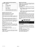
Thermostat Output Table

Table 4 depicts the L3711C thermostat output states for
various input conditions.

Table 4. L3711C Thermostat Outputs

Condition

W1

Y1

G

Gas Heat, Auto Fan

Heat Demand

X

Cool Demand

X

X

No Demand

Gas Heat, Continuous Fan

Heat Demand

X

X

Cool Demand

X

X

No Demand

X

Electric Heat, Auto Fan

Heat Demand

X

X

Cool Demand

X

X

No Demand

Electric Heat, Continuous Fan

Heat Demand

X

X

Cool Demand

X

X

No Demand

X

NOTE −  X =  output is activated with 24VAC.

Technical Specifications

Thermostat Type

Electronic programmable thermostat for 1-Stage
Heat/1-Stage Cool, gas or electric heat, non−heat pump,
non−power robbing applications.

Power Supply Range

18VAC − 30VAC (24VAC nominal), 60Hz

CAUTION

24VAC is present on the terminals of the thermostat
bracket. If removing the thermostat from the wall,
use caution and avoid touching any of the connec-
tor terminals  on the wall bracket.

Also, when working with the thermostat dip
switches, use a non−conductive tool and take cau-
tion to avoid making any contact with the circuit
board, its imprinted circuitry and its connector
prongs.

Temperature Display

Display Scale: Fahrenheit or Celsius user selectable (via
DIP switch; see figure 17)
Display range: 35°F (2°C) to 99°F (37°C)
Display resolution: 1°F (1°C)
Display Accuracy: +/−1°F

If the Fahrenheit/Celsius display must be changed, use a
plastic, non−conductive tool to push the dip switch to the
right position (see figure 17).

F/C (Fahrenheit/Celsius) switch
shown in Celsius position

1
2
3
4
5
6
7

PLUG IN (Use Care To Avoid Bending Prongs.)

Figure 17. Changing Fahrenheit/Celsius Setting

Indoor Temperature Measurement Range

Measurement Scale: Fahrenheit
Measurement Range: 35°F to 99°F
Measurement Resolution: 0.5°F
Measurement Accuracy: +/−1°F
Field Offset: via DIP switches to +/−3°F
Sampling Method: temperature measurements sampled
every 15 seconds. Displayed temperature is the average
of the last four measurements.

Outdoor Temperature Measurement Range

Measurement Scale: Fahrenheit
Measurement Range: −22°F to 122°F
Measurement Resolution: 1°F
Measurement Accuracy: +/−2°F

Temperature Setpoint Range

Setting range:  50°F (10°C) to 90°F (32°C)
Setting resolution: 1°F (1°C)

Smart Setback Recovery (via DIP switch #6)

Smart Setback Recovery (SSR) affects the way the ther-
mostat responds to program events. If SSR is disabled, the
thermostat will react to a program event at the time the
event occurs. However, if SSR is enabled, the thermostat
will react to a program event before the event occurs such
that the desired temperature is reached at the time of the
event, not after.

Autochangeover Deadband Selection (via DIP
switch #7)

Autochangeover deadband can be set to 4 or 6 degrees.
When autochangeover is enabled (via the AUTO button),
the thermostat will automatically change over from heating
to cooling and vice versa, to keep the room temperature in
between the heating and cooling setpoints. The deadband
is the minimum difference between the heating and cooling
setpoints.

Fan Control

AUTO or ON modes, gas or electric heat compatible via
DIP switches (also see Thermostat Output section).

I/O Relays

All thermostat relays are latching type to minimize power
consumption.

Summary of Contents for L3711C

Page 1: ...tochangeover Mode 3 HOLD Temperature Hold Mode 4 PROG Thermostat Programming 4 COPY Copy a Program 5 FAN Controlling Fan Operation 5 Displaying Outside Temperature 5 SETTINGS Filter Maintenance Reminder 5 Service Indicator 6 Thermostat RESET 6 Removing Installing Thermostat 6 Default Thermostat Settings 6 Thermostat Output Table 7 Technical Specifications 7 General These instructions are intended ...

Page 2: ...er input Start making changes within 15 seconds or the HOME screen will re turn Heat Prog Fan Settings Cool Day Time Hold Enter DOOR OPEN Auto Copy Outside Figure 3 Thermostat Buttons When an Arrow HOLD HEAT or COOL button is pressed SETPOINT and the temperature setting appears for 15 seconds If desired start making changes within 15 sec onds or the HOME screen will return The backlight will turn ...

Page 3: ...he right side of the display see figure 7 Heat Prog Fan Settings Cool Day Time Hold Enter DOOR OPEN Auto Copy Outside 66 i0 30 75 70 Figure 7 Turn Cool ON OFF If the thermostat is in cool mode pressing the COOL but ton disables cool mode indicated by OFF similar to figure 5 Cooling Demand Set the thermostat to cool mode to control the cooling equipment Then if the room temperature is higher than t...

Page 4: ...HOLD flashes see figure 9 This overrides the program for 2 hours from the last button press then returns to the program While in Temporary Hold press HOLD once to switch to Permanent Hold HOLD displays solid PROG not dis played press HOLD again to return to the program PROG displays HOLD not displayed Heat Prog Fan Settings Cool Day Time Hold Enter DOOR OPEN Auto Copy Outside 68 i0 30 72 70 Figure...

Page 5: ...ling the Fan Operation Use the FAN button to select either continuous fan mode or auto fan mode To change from continuous to auto fan mode or vice ver sa press the FAN button Note whether a fan icon in the FAN box is present indicating that the fan is running or not fan not running If continuous fan mode is enabled ON displayed in FAN box see figure 12 the fan will run continuously regard less of ...

Page 6: ...om a qualified service technician Thermostat RESET Under some abnormal conditions it may be necessary to reset the thermostat to its default condition Such a RE SET would delete all programming and settings and there fore should only be used on rare occasions when the the thermostat fails to function as designed and or as pro grammed Such an instance can occur as a result of a pow er surge or simi...

Page 7: ...shown in Celsius position 1 2 3 4 5 6 7 PLUG IN Use Care To Avoid Bending Prongs Figure 17 Changing Fahrenheit Celsius Setting Indoor Temperature Measurement Range Measurement Scale Fahrenheit Measurement Range 35 F to 99 F Measurement Resolution 0 5 F Measurement Accuracy 1 F Field Offset via DIP switches to 3 F Sampling Method temperature measurements sampled every 15 seconds Displayed temperatu...

Page 8: ...ce Reminder Settings of Off 6 or 12 months of chronological time are available When programmed time has elapsed a MAIN TENANCE indicator is displayed Service Reminder The SERVICE indicator is displayed only under the follow ing conditions S if the thermostat Y1 terminal has been activated with 24VAC for at least 5 minutes AND the L terminal is shorted to the R terminal OR S if the thermostat Y1 te...

Reviews: