Page 37
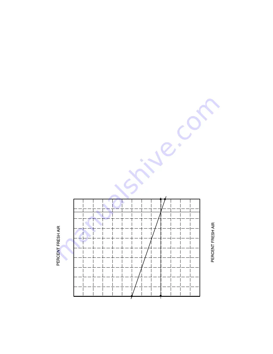
3- Measure outdoor air temperature. Mark the point on
the bottom line of chart 1 and label the point “A” (40
F,
4
C shown).
4- Measure return air temperature. Mark that point on
the top line of chart 1 and label the point “B” (74
F,
23
C shown).
5- Measure mixed air (outdoor and return air)
temperature. Mark that point on the top line of chart
1 and label point “C” (70
F, 21
C shown).
6- Draw a straight line between points A and B.
7- Draw a vertical line through point C.
8- Draw a horizontal line where the two lines meet. Read
the percent of fresh air intake on the side.
9- If fresh air percentage is less than desired, adjust MIN
POS SET potentiometer higher. If fresh air
percentage is more than desired, adjust MIN POS
SET potentiometer lower. Repeat steps 3 through 8
until calculation reads desired fresh air percentage.
10-Return economizer DIP switch to original position.
C-Economizer Operation
NOTE - Use indicating lights on Unit Controller to
determine thermostat demand.
See table 15 for economizer operation with a standard
two-stage thermostat
Table 16 shows economizer operation with an energy
management system which uses a global sensor.
Both tables show the occupied and unoccupied time
period. The occupied time period is determined by the
thermostat or energy management system.
Table 17 shows economizer operation in zone sensor
mode.
D-IAQ Damper Operation
The Unit Controller has a 0-10VDC IAQ input for a
standard 0-2000ppm CO
2
sensor. The economizer
starts opening at a CO
2
level of 500 ppm (default) and
reaches full open at a CO
2
level of 1000ppm. These
levels are adjustable as outlined in the Unit Controller
manual under the menu
Settings>Setpoints>IAQ.
If the economizer is operating in the free cooling mode
and the IAQ sensor demands more fresh air, the IAQ
demand will override the free cooling demand to open the
dampers further or to keep them open. A flashing OAS
LED on the Unit Controller indicates an IAQ override
condition.
The IAQ function is not energized during the unoccupied
or night time period.
-20
-29
-10
-23
0
-18
10
-12
20
-7
30
-1
40
4
50
10
60
16
70
21
80
27
90
32
100
38
0
10
30
40
50
60
70
80
90
100
20
OUTDOOR AIR TEMPERATURE
0
10
30
40
50
60
70
80
90
100
20
CHART 1
CALCULATE MINIMUM FRESH AIR PERCENTAGE
(MIXED AND RETURN AIR TEMPERATURE)
A
B
C
F
C
F
C
-20
-29
-10
-23
0
-18
10
-12
20
-7
30
-1
40
4
50
10
60
16
70
21
80
27
90
32
100
38
F
C
F
C


