background image

Page 33

LGH/LCH036, 048, 060, 072

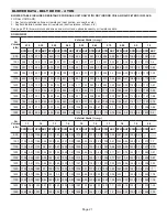
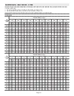
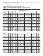
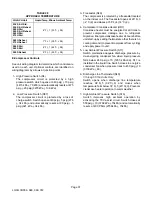
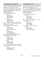
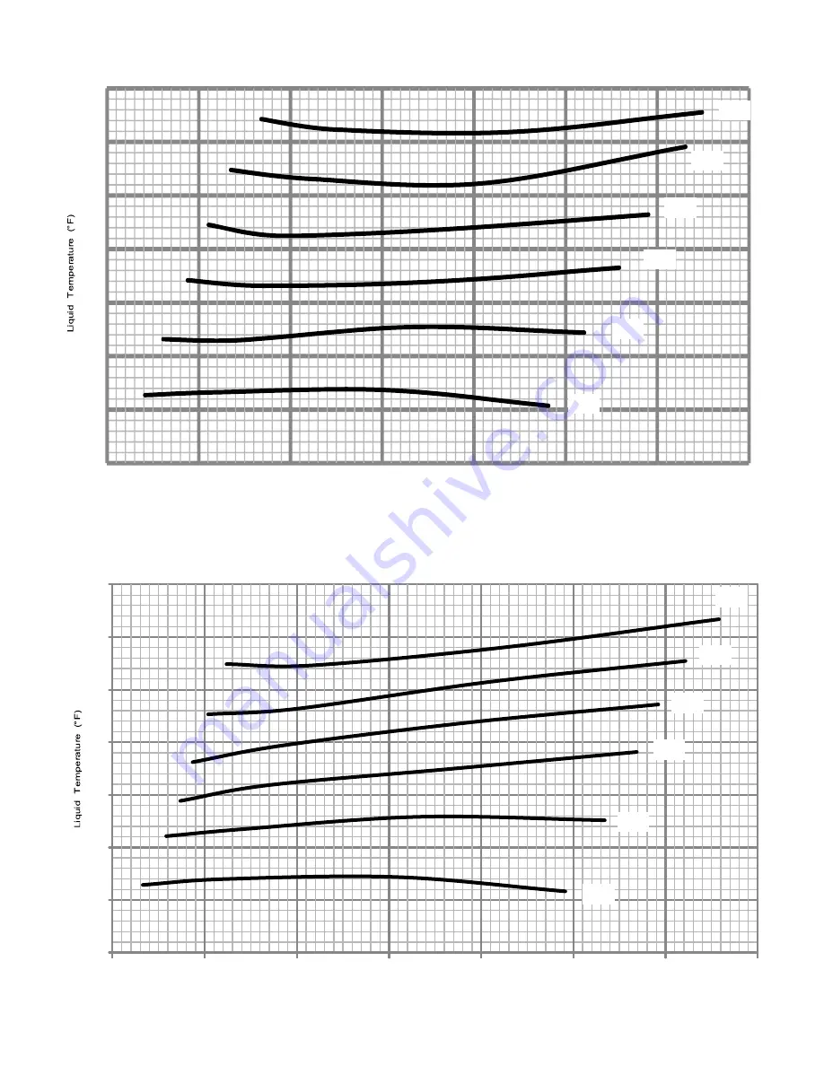
LGH/LCH060S CHARGING CURVE - ALL-ALUMINUM COIL

60

70

80

90

100

110

120

130

110

120

130

140

150

160

Outdoor Temperature (°F)

170

180

Suction Pressure (psig)

105°

95°

115°

85°

75°

65°

60

70

80

90

100

110

120

130

110

120

130

140

150

160

Outdoor Temperature (°F)

170

180

Suction Pressure (psig)

105°

95°

115°

85°

75°

65°

LGH/LCH060H CHARGING CURVE - ALL-ALUMINUM COIL

Summary of Contents for LCH 036

Page 1: ...Gas Piping Page 8 Pressure Test Gas Piping Page 9 INSTALLATION INSTRUCTIONS LGH LCH036 048 060 072 3 4 5 and 6 Ton GAS AND COOLING PACKAGED UNITS 507410 02 12 2014 Supersedes 8 2014 High Altitude Dera...

Page 2: ...NING BOTTOM CONDENSATE OUTLET 25 3 4 654 BOTTOM POWER ENTRY 3 X 8 76 X 203 18 3 8 467 19 1 2 495 5 1 2 140 FORKLIFT SLOTS Front Back and Blower End HORIZONTAL RETURN AIR OPENING Without Economizer HOR...

Page 3: ...ALVE BURNERS COMBUSTION AIR INDUCER BLOWER MOTOR BELT DRIVE SHOWN TXV UNIT CONTROLLER REHEAD COIL OPTIONAL BLOWER COIL GUARDS OPTIONAL LCH036 048 060 072 PARTS ARRANGEMENT ELECTRIC HEAT Optional EVAPO...

Page 4: ...enance IMPORTANT The Clean Air Act of 1990 bans the intentional vent ing of refrigerant CFC s and HCFC s as of July 1 1992 Approved methods of recovery recycling or reclaiming must be followed Fines a...

Page 5: ...upports must be high enough to prevent any form of moisture from entering unit Recommended minimum frame height is 14 356mm 4 Duct must be attached to the roof mounting frame and not to the unit Suppl...

Page 6: ...rn air duct beneath outdoor air intake See figure 4 Install barometric relief damper in lower hood and install in ductwork as shown in figure 4 FIGURE 4 HORIZONTAL RETURN AIR DUCTWORK WITH ECONOMIZER...

Page 7: ...ont edge of the drain pan and slide pan out of unit See figure 9 FIGURE 9 REMOVE DRAIN PAN DRAIN PAN 3 Make sure the cap over the unit bottom drain hole is secure 4 Rotate the drain pan until the down...

Page 8: ...LP Propane Gas Min Max Min Max 036 072 4 5 10 5 11 13 When making piping connections a drip leg should be installed on vertical pipe runs to serve as a trap for sediment or condensate A 1 8 N P T plu...

Page 9: ...of ignition to check for leaks NOTE In case emergency shut down is required turn off the main manual shut off valve and disconnect main power to unit These devices should be properly labeled by the in...

Page 10: ...operate the unit from a thermostat or zone sensor based on the System Mode The default System Mode is the thermostat mode Refer to the Unit Controller Installation and Setup Guide to change the Syste...

Page 11: ...igure 15 for Zone Sensor Mode In addition connect either a humidity sensor or a dehumidification input See figure 16 or 17 for humidity sensor wiring or figure 18 for dehumidification input wiring Hum...

Page 12: ...anced Air Flow Control Start Up section T Units are equipped with a two stage belt drive blower B Units are equipped with a single stage belt drive blower Note Six ton units are available with belt dr...

Page 13: ...centage torque for indoor blower smoke speed Installer Circle applicable unit model number and record any parameter changes under Field Setting column Settings need to be recorded by installer for use...

Page 14: ...unting frame See figure 20 2 To increase belt tension Slide blower motor downward to tighten the belt This increases the distance between the blower motor and the blower housing 3 To loosen belt tensi...

Page 15: ...oned belt H Field Furnished Blower Drives For field furnished blower drives use page 19 through 26 to determine BHP and RPM required Reference Page 27 to determine the drive kit number Reference table...

Page 16: ...100 0 9 676 178 979 884 229 1006 1092 280 1033 1237 342 1061 1381 404 1088 1513 472 1105 1645 539 1121 1 0 605 187 1011 819 240 1049 1032 294 1087 1192 353 1100 1352 411 1112 1474 480 1137 1595 549 11...

Page 17: ...0 0 9 1162 304 1060 1367 401 1097 1572 498 1134 1741 603 1168 1909 708 1202 2009 792 1223 2109 875 1244 1 0 1133 316 1104 1333 414 1136 1533 511 1167 1702 612 1198 1870 714 1229 1959 791 1251 2047 868...

Page 18: ...9 1211 337 964 1462 437 988 1714 538 1012 1902 669 1053 2090 801 1094 2237 942 1127 2383 1084 1161 1 0 1151 354 1013 1412 454 1029 1672 553 1045 1871 682 1078 2069 811 1112 2211 955 1149 2352 1099 11...

Page 19: ...27 831 0 3 886 0 32 931 0 36 978 0 38 1028 0 41 1078 0 43 1200 574 0 2 643 0 24 711 0 27 784 0 3 852 0 33 904 0 36 947 0 39 993 0 42 1042 0 45 1091 0 47 1300 608 0 24 676 0 28 743 0 31 812 0 34 875 0...

Page 20: ...7 0 23 789 0 26 848 0 3 903 0 33 954 0 37 1003 0 4 1052 0 43 1200 544 0 17 613 0 21 682 0 24 748 0 27 809 0 29 866 0 33 918 0 37 967 0 4 1014 0 43 1062 0 46 1300 572 0 21 640 0 24 707 0 27 771 0 3 830...

Page 21: ...840 0 45 893 0 49 940 0 53 980 0 57 1019 0 61 1060 0 64 1104 0 67 1147 0 7 1187 0 74 1800 821 0 47 874 0 51 923 0 55 967 0 59 1006 0 63 1044 0 67 1085 0 7 1128 0 73 1170 0 77 1208 0 82 1900 857 0 53 9...

Page 22: ...839 0 45 891 0 49 935 0 53 975 0 58 1017 0 62 1060 0 65 1104 0 68 1147 0 72 1800 761 0 42 816 0 46 868 0 5 916 0 55 957 0 59 997 0 64 1038 0 68 1081 0 71 1124 0 74 1165 0 79 1900 795 0 48 848 0 52 89...

Page 23: ...2200 922 0 60 958 0 65 994 0 71 1031 0 76 1068 0 82 1106 0 87 1143 0 91 1180 0 95 1218 0 99 1255 1 03 2300 947 0 67 983 0 73 1020 0 79 1057 0 85 1094 0 90 1131 0 95 1168 1 00 1205 1 03 1242 1 07 1277...

Page 24: ...0 73 1024 0 78 1060 0 83 1097 0 87 1135 0 90 1173 0 94 1210 0 98 2300 909 0 64 942 0 70 976 0 75 1011 0 81 1046 0 86 1083 0 91 1120 0 95 1157 0 98 1195 1 02 1231 1 06 2400 931 0 72 965 0 78 999 0 83 1...

Page 25: ...658 0 88 687 0 94 717 1 746 1 05 775 1 11 802 1 16 829 1 22 853 1 27 877 1 31 901 1 36 2800 679 0 95 708 1 01 736 1 07 764 1 12 792 1 18 819 1 24 844 1 3 868 1 35 892 1 39 915 1 43 2900 701 1 02 728...

Page 26: ...1 1 25 2700 624 0 96 653 0 99 682 1 02 712 1 06 741 1 09 769 1 13 796 1 18 823 1 22 849 1 27 873 1 32 2800 645 1 02 673 1 05 701 1 09 730 1 12 758 1 16 785 1 2 812 1 25 838 1 29 862 1 34 886 1 39 2900...

Page 27: ...0 04 0 07 1200 0 03 0 04 0 01 0 02 0 02 0 04 0 04 0 07 1400 0 04 0 05 0 02 0 02 0 03 0 04 0 04 0 07 1600 0 05 0 06 0 03 0 03 0 04 0 04 0 04 0 07 1800 0 06 0 07 0 04 0 04 0 05 0 05 0 04 0 07 2000 0 08...

Page 28: ...th Unit Controller Installation and Setup Guide Use the menu navigation arrows and select button see SERVICE TEST 2 No Economizer Installed in Unit A first stage cooling demand Y1 will energize the co...

Page 29: ...sured liquid temperature is lower than the target liquid temperature recover some refrigerant from the system 5 Add or remove charge in increments Allow the system to stabilize each time refrigerant i...

Page 30: ...75 F 85 F 95 F 105 F 115 F Suct psig Disc psig Suct psig Disc psig Suct psig Disc psig Suct psig Disc psig Suct psig Disc psig Suct psig Disc psig 114 249 116 287 119 330 121 376 123 425 127 482 122 2...

Page 31: ...90 100 110 120 130 110 120 130 140 150 160 170 180 Outdoor Temperature F Suction Pressure psig 105 95 115 85 75 65 60 70 80 90 100 110 120 130 110 120 130 140 150 160 Outdoor Temperature F 170 180 Su...

Page 32: ...Pressure psig 60 70 80 90 100 110 120 130 110 120 130 140 150 160 Outdoor Temperature F 170 180 105 95 115 85 75 65 LGH LCH048H CHARGING CURVE ALL ALUMINUM COIL Suction Pressure psig 60 70 80 90 100 1...

Page 33: ...90 100 110 120 130 110 120 130 140 150 160 Outdoor Temperature F 170 180 Suction Pressure psig 105 95 115 85 75 65 60 70 80 90 100 110 120 130 110 120 130 140 150 160 Outdoor Temperature F 170 180 Su...

Page 34: ...Page 34 LGH LCH036 048 060 072 LGH LCH072H CHARGING CURVE ALL ALUMINUM COIL Suction Pressure psig 60 70 80 90 100 110 120 130 110 120 130 140 150 160 Outdoor Temperature F 170 180 105 95 115 85 75 65...
Page 35: ...oceeding 5 If discharge pressure is high remove refrigerant from the system If discharge pressure is low add refrigerant to the system Add or remove charge in increments Allow the system to stabilize...

Page 36: ...5 1155 F 479 148 TABLE 25 LG LC 060H REHEAT NORMAL OPERATING PRESSURES Outdoor Coil Entering Air Temp Discharge 10 psig Suction 5 psig 655 F 256 136 755 F 295 138 855 F 337 140 955 F 384 143 1055 F 43...

Page 37: ...on the indoor coil The freezestat opens at 29 F 3 2 C 2 and closes at 58 F 4 14 C 2 4 Compressor Crankcase Heater HR1 Crankcase heater must be energized at all times to prevent compressor damage due t...

Page 38: ...hermostat OR Room Sensor 1 Economizer With Outdoor Air Suitable Y1 Demand Compressors Off Blower Cooling Low Dampers modulate Y2 Demand Compressors Off Blower Cooling High Dampers Modulate Note If dam...

Page 39: ...l lever or gas control knob Use only your hand to push the lever or turn the gas control knob Never use tools If the the lever will not move or the knob will not push in or turn by hand do not try to...

Page 40: ...Adjustments Gas Units A Heating Sequence of Operation 1 On a heating demand the combustion air inducer starts immediately 2 Combustion air pressure switch proves inducer operation After a 30 second pr...

Page 41: ...h to enter each supply air CFM into the Unit Controller Make sure supply air CFM is within limitations shown in table 31 Refer to the Unit Controller manual provided with unit SETTING RTU OPTIONS BLOW...

Page 42: ...ve an occupied OCP thermostat demand TABLE 31 MINIMUM MAXIMUM CFM LGH LCH036 060 Unit Parameter Settings Parameter Name LCH LGH Default Factory Settings 036H4E 048H4E 060H4E SETUP TEST BALANCE BLOWER...

Page 43: ...ode of operation These units contain a reheat coil adjacent to and downstream of the evaporator coil Reheat coil solenoid valve L14 routes hot discharge gas from the compressor to the reheat coil Retu...

Page 44: ...all for dehumidification Compressor is operating blower is on and the reheat valve is energized Y1 demand Compressor is operating blower is on and the reheat valve is energized Y2 demand Compressor is...

Page 45: ...All motors are lubricated at the factory No further lubrication is required C Burners Gas Units Periodically examine burner flames for proper appearance during the heating season Before each heating...

Page 46: ...combustion air inducer port 4 Remove and retain screws securing combustion air inducer to flue box Remove vent connector See figure 34 5 Clean inducer wheel blades with a small brush and wipe off any...

Page 47: ...between the slabs To clean between slabs carefully separate coil slabs and wash them thoroughly See figure 35 Flush coils with water following cleaning Note Remove all screws and gaskets prior to cle...

Page 48: ...ngs Use menu SETUP NETWORK INTEGRATION Set BACNET and network address BACNET MAC ADDRESS TABLE 34 580732 Units With Room Sensor CPC LSE Gateway Settings Use menu SETUP NETWORK INTEGRATION Set L CONNEC...

Page 49: ...d U Power Exhaust 3 Not Installed N Single Stage S Dual Stage D Unconfigured U Power Exhaust Control 4 Not Installed N Damper Position A 5 Network Module N Not Installed B BACnet L LonTalk Lennox 6 Bl...

Page 50: ...Not Installed Y Installed 8 Load Shedding N Not Installed G Global P297 pin 9 L Installed on DI 2 U Installed on DI 3 9 Electric Heat Field Installed 1 Air Flow Proving Switch S52 3 Overflow Switch S...

Page 51: ...ge 7 Condensate Drains Page 7 Gas Piping Page 9 Pressure Test Gas Piping Page 10 High Altitude Derate Page 11 Electrical Connections Page 11 Blower Operation and Adjustments Page 14 INSTALLATION INSTR...

Page 52: ...10 3 4 273 CENTER OF GRAVITY TOP VIEW BOTTOM RETURN AIR OPENING 24 610 5 5 8 143 6 1 8 156 6 1 8 156 6 5 8 168 28 711 27 686 20 508 AA DD EE FF BOTTOM BASE BASE CONDENSATE 101 1 4 2572 BB CC BOTTOM S...

Page 53: ...8 1527 CENTER OF GRAVITY TOP VIEW BOTTOM RETURN AIR OPENING 24 610 5 5 8 143 6 1 8 156 6 1 8 156 6 5 8 168 28 711 27 686 20 508 AA DD EE FF BOTTOM CONDENSATE 124 3 8 3159 BB CC BOTTOM SUPPLY AIR OPEN...

Page 54: ...ITS WITH DIRECT DRIVE BLOWER HINGED ACCESS PANEL OPTIONAL OUTDOOR FAN TRANSFORMER 094 122 152 460V OR 570V UNITS LCH092 094 102 120 122 150 152 PARTS ARRANGEMENT OUTDOOR FAN TRANSFORMER 094 122 152 46...

Page 55: ...nverter Standard and high efficiency units are available with a belt drive blower equipped with an optional supply air inverter The blower will operate at lower speeds when demand is low and increase...

Page 56: ...stallation instructions Unit Support In downflow discharge installations install the unit on a non combustible surface only Unit may be installed on combustible surfaces when used in horizontal discha...

Page 57: ...ing 4 Place field provided H style pick in place just above top edge of unit Frame must be of adequate strength and length H style pick prevents damage to unit Condensate Drains Make drain connection...

Page 58: ...er access door Refer to figure 6 REMOVE THREE SCREWS PER HINGE FIGURE 6 CONDENSATE DRAIN MULLION UNITS WITH HINGED PANELS FILTER DOOR 3 Open filter access door hinges and carefully remove door 4 Remov...

Page 59: ...Replace the condensate drain mullion and reinstall eight screws 14 Reinstall filter door on hinges Connect Gas Piping Gas Units Before connecting piping check with gas company or authorities having ju...

Page 60: ...main shut off valve and union furnished by installer be installed in gas line external to unit Union must be of the ground joint type After all connections have been made check all piping connections...

Page 61: ...ronic controls Pre cautions will help to avoid control exposure to elec trostatic discharge by putting the unit the control and the technician at the same electrostatic poten tial Neutralize electrost...

Page 62: ...mode Make room sensor wiring connections as shown in figure 13 C Hot Gas Reheat Units Only 1 Install humidity sensor in accordance with instructions provided with sensor A DDC input may be used to in...

Page 63: ...ly power to RH sensor as shown in figure 16 Use two shielded cables containing 20AWG minimum twisted pair conductors with overall shield Belden type 8762 or 88760 plenum or equivalent FIGURE 15 FIELD...

Page 64: ...e is incorrect the Unit Controller will display an alarm and the unit will not start A Blower Operation Note On units with staged blowers use the Unit Controller to start the blower Refer to the appro...

Page 65: ...MOTOR MOUNTING BASE LOOSEN BEFORE ADJUSTING BELT TENSION TWO EACH SIDE REMOVE TWO SCREWS ON EACH SIDE TO SLIDE FRAME PARTIALLY OUT OF UNIT FOR SERVICE ACCESS MOTOR BLOWER HOUSING BLOWER FRAME GAP BETW...

Page 66: ...surements are taken 2 With all access panels in place measure static pressure external to unit from supply to return Blower performance data is based on static pressure readings taken in locations sho...

Page 67: ...adjusting bolt to the left or counterclockwise to loosen belt tension IMPORTANT Align edges of blower motor base and mounting frame base parallel before tightening four bolts on the side of base Moto...

Page 68: ...82 1166 1 95 2000 493 0 29 561 0 47 629 0 64 700 0 77 768 0 9 832 1 02 892 1 17 946 1 33 995 1 49 1041 1 66 1085 1 81 1126 1 97 1167 2 12 2250 507 0 37 574 0 56 643 0 72 712 0 86 779 0 99 842 1 13 900...

Page 69: ...05 2 29 1154 2 47 1206 2 68 3000 564 0 66 626 0 84 692 1 01 759 1 16 819 1 32 874 1 49 924 1 68 971 1 88 1017 2 08 1063 2 26 1110 2 44 1158 2 63 1208 2 83 3250 585 0 79 648 0 98 714 1 14 778 1 31 836...

Page 70: ...931 1261 1060 1307 1198 1351 1341 1395 1489 3750 1185 806 1232 931 1277 1063 1322 1201 1365 1348 1407 1499 1448 1657 4000 1254 937 1299 1072 1341 1214 1383 1363 1424 1518 1464 1679 1503 1844 4250 1324...

Page 71: ...ELD INSTALLED ACCESSORY AIR RESISTANCE in w g Air Volume cfm Wet Indoor Coil Gas Heat Exchanger Electric Heat Econo mizer Humiditrol Condenser Reheat Coil Filters Return Air Adaptor Plate Standard Hea...

Page 72: ...X1 1 8 100239 07 BK77X1 49K4001 BX68 88K3401 8T 1VP56X1 1 8 P 8 1492 BK85X1 49K4101 BX70 31K9601 9T 1VP50X1 1 8 P 8 1977 BK67X1 100244 24 BX66 88K3301 10T 1VP50X1 1 8 P 8 1977 BK77X1 49K4001 BX68 88K3...

Page 73: ...ing pressures The gauges should be rated for use with pressures of 0 800 on the high side and a low side of 30 vacuum to 250 psi with dampened speed to 500 psi Gauge hoses must be rated for use at up...

Page 74: ...omponents if there are significant differences 3 Measure the outdoor ambient temperature and the suction pressure Refer to the appropriate circuit charging curve to determine a target liquid temperatu...

Page 75: ...31 488 139 241 143 280 143 319 146 368 147 417 150 483 158 254 161 287 167 328 168 370 171 426 174 480 TABLE 8 LGH LCH120H Normal Operating Pressures All Aluminum TXV Outdoor Coil Entering Air Tempera...

Page 76: ...on Pressure psig Outdoor Temperature F 115 105 95 85 75 65 LGH LCH092H4 Charging Curves All Aluminum TXV 60 70 80 90 100 110 120 130 Suction Pressure psig Liquid Temperature F LGH LCH102H Charging Cur...

Page 77: ...quid Temperature F LGH LCH120H Charging Curves All Aluminum TXV Circuit 1 Circuit 2 Outdoor Temperature F Suction Pressure psig 115 105 95 85 75 65 60 70 80 90 100 110 120 130 100 110 120 130 140 150...

Page 78: ...component in the system Correct any system problems before proceeding 6 If discharge pressure is high remove refrigerant from the system If discharge pressure is low add refrigerant to the system Add...

Page 79: ...35 141 855 F 360 142 376 143 955 F 407 144 420 144 1055 F 455 147 466 147 1155 F 510 150 518 150 Charge Verification Approach Method AHRI Testing Fin Tube Coil Continued 1 Using the same thermometer c...

Page 80: ...in the outdoor section If measured liquid temperature is higher than the target liquid temperature add refrigerant to the system If measured liquid temperature is lower than the target liquid temperat...

Page 81: ...Suction Pressure psig 115 105 95 85 75 65 60 70 80 90 100 110 120 130 100 110 120 130 140 150 160 170 Liquid Temperature F LGH LCH150S Charging Curves Fin Tube RFC Circuit 1 Circuit 2 Outdoor Tempera...

Page 82: ...nces in installations Significant differences could mean that the system is not properly charged or that a problem exists with some component in the system Correct any system problems before proceedin...

Page 83: ...ains adequate discharge pressure by de energizing condenser fans when liquid pressure falls below 240 psig 10 1655 kPa 69 S11 is installed in the liquid line Switch closes to energize condenser fan wh...

Page 84: ...turn the gas control knob Never use tools If the knob will not push in or turn by hand do not try to repair it call a qualified service technician Force or attempted repair may result in a fire or ex...

Page 85: ...sensor proves the flame and combustion continues 5 If flame is not detected after first ignition trial ignition control will repeat steps 3 and 4 two more times before locking out the gas valve 6 For...

Page 86: ...U Options EDIT PARAMETER ENTER DATA ID 9 MIN DAMPER LOW BLOWER X X Measure the intake air CFM If the CFM is lower than the design specified CFM for ventilation air use the Unit Controller to increase...

Page 87: ...ton Unit Blower Speed Airflow CFM LGH LCH092 High 3600 LGH LCH102 High 4080 LGH LCH120 High 4800 LGH LCH150 High 6000 TABLE 25 MINIMUM AND MAXIMUM CFM BELT DRIVE ULTRA HIGH EFFICIENCY BLOWERS 094U4M 1...

Page 88: ...o fill in field provided design specified blower CFM TABLE 26 Blower CFM Design Specifications Blower Speed Design Specified CFM Heating Cooling High Cooling Low Ventilation 2 Use the following menu t...

Page 89: ...R POSITION BLOWER ON HIGH X X Measure the intake air CFM If the CFM is lower than the design specified CFM for ventilation air use the Unit Controller to increase the damper percent open If the CFM is...

Page 90: ...efrigerant routing and figure 30 for standard cooling refrigerant routing REHEAT COIL FIGURE 29 REHEAT MODE REFRIGERANT ROUTING STAGE 1 CONDENSER COIL STAGE 2 CONDENSER COIL STAGE 2 EVAPORATOR COIL ST...

Page 91: ...Humid ity Demands Operation Reheat Only Compressor 1 Reheat Reheat Y1 Compressor 1 Reheat Compressor 2 Cooling Reheat Y1 Y2 Compressor 1 Cooling Compressor 2 Cooling If there is no reheat demand and...

Page 92: ...D Combustion Air Inducer Gas Units A combustion air proving switch checks combustion air inducer operation before allowing power to the gas controller Gas controller will not operate if inducer is obs...

Page 93: ...Flue Box Gas Units 1 Remove combustion air inducer assembly as described in section D 2 Remove flue box cover Clean with a wire brush as required 3 Remove inserts if installed See figure 36 4 Clean tu...

Page 94: ...to fracture the braze between the fins and refrigerant tubes Reduce pressure and work cautiously to prevent damage Fin Tube Coils Clean condenser coil annually with detergent or commercial coil clean...

Page 95: ...60 Time delay between heating and cool ing mode TABLE 33 580733 Units With BACnet Module Kohl s Settings Use menu SETUP NETWORK INTEGRATION Set BACNET and network address BACNET MAC ADDRESS Para meter...

Page 96: ...power exhaust operation TABLE 36 580686 LGH LCH094U4M 122U4M 152U4M 2 Compressor Staged Belt Drive Paramet er Factory Setting Field Setting Description 094 122 152 Note Any changes to Smoke CFM setti...

Page 97: ...g HIGH blower operation SETTINGS RTU OPTIONS EDIT PARAMETERS 29 101 Open Damper minimum position during G blower operation Setting para meter 29 to 101 disables para meter 29 and passes control to par...

Page 98: ...wer settings are entered the target highest of the heating and cooling settings CFM will be displayed Once the RPM is saved for the target CFM all other blower RPM values are set by the Unit Controlle...

Page 99: ...haust 3 Not Installed N Single Stage S Dual Stage D Unconfigured U Power Exhaust Control 4 Not Installed N Damper Position A 5 Network Module N Not Installed B BACnet L LonTalk Lennox 6 Blower Variabl...

Page 100: ...ed Y Installed 8 Load Shedding N Not Installed G Global P297 pin 9 L Installed on DI 2 U Installed on DI 3 9 Electric Heat Field Installed 1 Air Flow Proving Switch S52 3 Overflow Switch S149 S179 4 M...

Page 101: ...ensate Drains Page 5 Gas Piping Page 5 Pressure Test Gas Piping Page 6 High Altitude Derate Page 7 Factory Installed Options Page 7 Electrical Connections Page 8 Blower Operation and Adjustments Page...

Page 102: ...BOTTOM RETURN AIR OPENING 108 28 711 28 711 9 229 17 1 2 CONDENSATE DRAIN 137 83 GAS SUPPL Y INLET For Bottom Gas Supply Only OPTIONAL DISCONNECT Factory Installed SIDE ELECTRICAL INLETS 102 OPTIONAL...

Page 103: ...these installation instructions A room thermostat must control the unit The use of fixed jumpers that will provide continuous heating or cooling is not allowed A pre filter must be installed at the en...

Page 104: ...plenums must be installed before setting the unit Installer s Roof Mounting Frame Many types of roof frames can be used to install the unit depending upon different roof structures Items to keep in mi...

Page 105: ...cal codes concerning condensate disposal Refer to pages 1 and 2 for condensate drain location Note The drain pan is made with a glass reinforced engineered plastic capable of withstanding typical join...

Page 106: ...nished by installer be installed in gas line external to unit Union must be of the ground joint type After all connections have been made check all piping connections for gas leaks Also check existing...

Page 107: ...Install as follows 1 Remove left side from hood top panel See figure 7 REMOVE LEFT SIDE OF HOOD FROM UNIT FIGURE 7 HOOD TOP PANEL LEFT SIDE LONGER FRONT BRACKET SHORTER FRONT BRACKET 2 Remove and ret...

Page 108: ...et 1524mm above the floor in an area with good air circulation at average temperature Avoid locating the room thermostat where it might be affected by drafts or dead spots behind doors and in corners...

Page 109: ...E 12 FIELD WIRING IN ZONE SENSOR MODE Zone Sensor Mode A2 SENSOR OUTPUTS SENSOR SENSOR 24VAC R C IAQ HUM AI1 D01 TMP D02 UNIT CONTROLLER J298 3 Third Party Zoning The Unit Controller will operate up t...

Page 110: ...m and the unit will not start Refer to the Unit Controller manual for details A Blower Operation Initiate blower only G demand at thermostat according to instructions provided with thermostat Unit wil...

Page 111: ...will allow belt to stretch and seat grooves Make sure blower and motor pulley are aligned See figure 16 for blowers not equipped with a tensioner and figure 17 for blowers equipped with an optional t...

Page 112: ...force to center of span X with enough pressure to deflect belt 1 64 for every inch of span length or 1 5mm per 100mm of span length Example Deflection distance of a 40 span would be 40 64 or 5 8 Exam...

Page 113: ...64 4 11 901 4 48 937 4 83 971 5 19 1008 5 59 7500 453 1 46 513 1 79 579 2 14 641 2 55 696 2 88 747 3 24 792 3 63 833 4 04 872 4 45 909 4 83 945 5 20 979 5 56 1016 5 97 8000 467 1 66 528 2 00 593 2 38...

Page 114: ...27 11500 0 39 0 37 0 48 0 55 0 07 0 08 0 02 0 08 0 30 12000 0 41 0 40 0 52 0 60 0 07 0 10 0 02 0 08 0 33 12500 0 44 0 44 0 57 0 65 0 08 0 11 0 03 0 10 0 37 13000 0 47 0 48 0 61 0 70 0 08 0 13 0 03 0 1...

Page 115: ...al is not observed or blower rota tion is not correct 3 Disconnect all remote electrical power supplies 4 Reverse any two field installed wires connected to the line side of S48 disconnect or TB13 ter...

Page 116: ...Adjustment section for proper method to check refrigerant charge EVAPORATOR COIL STAGE 1 CONDENSER COIL FIGURE 20 STAGE 2 CONDENSER COIL STAGE 1 EVAPORATOR COIL STAGE 2 EVAPORATOR COIL CAV REFRIGERANT...

Page 117: ...il is clean Attach gauge manifolds and operate unit at full CFM in cooling mode with economizer disabled until system stabilizes approximately five minutes Make sure all outdoor air dampers are closed...

Page 118: ...39 475 150 244 149 277 150 325 153 370 156 421 159 476 169 254 172 289 172 331 174 379 178 428 180 482 TABLE 6 LGH LCH300H CAV Normal Operating Pressures Outdoor Coil Entering Air Temperature 65 F 75...

Page 119: ...136 512 143 283 145 319 148 364 151 405 154 455 156 519 151 288 165 327 169 369 173 419 176 466 179 525 TABLE 8 LGH LCH360 CAV Normal Operating Pressures Outdoor Coil Entering Air Temperature 65 F 75...

Page 120: ...425 147 473 152 544 Circuit 2 97 257 100 303 102 349 104 385 106 447 107 524 104 256 107 305 110 353 112 399 115 451 117 523 121 270 125 313 128 355 130 397 134 454 134 521 135 280 140 322 145 364 14...

Page 121: ...Outdoor Temperature F 115 105 95 85 75 65 LGH LCH242 VAV Circuit 1 Charging Curve Liquid Temperature F 60 70 80 90 100 110 120 130 90 100 110 120 130 140 150 160 Suction Pressure psig Outdoor Tempera...

Page 122: ...Outdoor Temperature F 115 105 95 85 75 65 LGH LCH242 VAV Circuit 3 Charging Curve Liquid Temperature F 60 70 80 90 100 110 120 130 110 120 130 140 150 160 170 180 Suction Pressure psig Outdoor Temper...

Page 123: ...115 105 95 85 75 65 Outdoor Temperature F Liquid Temperature F LGH LCH300H CAV Circuit 1 Charging Curve 60 70 80 90 100 110 120 130 100 110 120 130 140 150 160 170 Suction Pressure psig 115 105 95 85...

Page 124: ...ction Pressure psig Outdoor Temperature F Liquid Temperature F LGH LCH300H CAV Circuit 3 Charging Curve 60 70 80 90 100 110 120 130 100 110 120 130 140 150 160 170 Suction Pressure psig Liquid Tempera...

Page 125: ...Outdoor Temperature F Liquid Temperature F 115 105 95 85 75 65 LGH LCH300H VAV Circuit 1 Charging Curve 60 70 80 90 100 110 120 130 100 110 120 130 140 150 160 170 Suction Pressure psig Outdoor Temper...

Page 126: ...g Outdoor Temperature F Liquid Temperature F 115 105 95 85 75 65 LGH LCH300H VAV Circuit 3 Charging Curve 60 70 80 90 100 110 120 130 110 120 130 140 150 160 170 180 Suction Pressure psig Outdoor Temp...

Page 127: ...Outdoor Temperature F Liquid Temperature F 115 105 95 85 75 65 LGH LCH360 CAV Circuit 1 Charging Curve 60 70 80 90 100 110 120 130 90 100 110 120 130 140 150 160 170 Suction Pressure psig Outdoor Tem...

Page 128: ...Outdoor Temperature F Liquid Temperature F 115 105 95 85 75 65 LGH LCH360 CAV Circuit 3 Charging Curve 60 70 80 90 100 110 120 130 90 100 110 120 130 140 150 160 170 Suction Pressure psig Outdoor Tem...

Page 129: ...ig Outdoor Temperature F Liquid Temperature F 115 105 95 85 75 65 LGH LCH360 VAV Circuit 1 Charging Curve 60 70 80 90 100 110 120 130 90 100 110 120 130 140 150 160 Suction Pressure psig Outdoor Tempe...

Page 130: ...ig Outdoor Temperature F Liquid Temperature F 115 105 95 85 75 65 LGH LCH360 VAV Circuit 3 Charging Curve 60 70 80 90 100 110 120 130 110 120 130 140 150 160 170 180 Suction Pressure psig Outdoor Temp...

Page 131: ...a Y2 cooling demand Condenser fans 1 2 5 and 6 are energized after a 2 second delay See figure 22 Condenser fans 2 and 5 are de energized when outdoor temperature drops below 55 F 13 C Condenser fans...

Page 132: ...hown in OFF position FIGURE 23 LOW FIRE ADJUSTMENT HIGH FIRE ADJUSTMENT INLET PRESSURE TAP 5 Turn the knob on the gas valve clockwise to OFF Do not force 6 Wait five minutes to clear out any gas If yo...

Page 133: ...are factory set and do not require adjustment Gas manifold pressures should match pressures shown in table 10 TABLE 10 Natural Gas Propane LP Gas 1st Stage 0 2 2nd Stage 0 3 1st Stage 0 2 2nd Stage 0...

Page 134: ...13 Note The Unit Controller will lock out the unit for 5 minutes if static pressure exceeds 2 0 w c for 20 seconds The Unit Controller will permanently shut down the unit after three occurrences See U...

Page 135: ...ee figure 29 P248 Jumper Plug J248 FIGURE 29 SUPPLY AIR VFD BY PASS CONNECTOR P248 J248 Disconnect Connect 6 Locate VFD control relay K203 on the lower control panel next to terminal strip TB24 See fi...

Page 136: ...too humid to enter the system adjust the setting lower B C or D Table 14 shows the approximate enthalpy control temperature setpoints at 50 relative humidity TABLE 14 Control Setting Enthalpy Control...

Page 137: ...an energy management system which uses a global sensor Both tables show the occupied and unoccupied time period The occupied time period is determined by the thermostat or energy management system Tab...

Page 138: ...ALPY DAMPER MOTOR J193 JACK ENTHALPY SENSOR J298A JACK IAQ INTERFACE J262A JACK DAMPER MOTOR J262B JACK ENTHALPY SENSORS P3 PLUG ECONOMIZER BYPASS P153 PLUG ENTHALPY DAMPER MOTOR P193 PLUG ENTHALPY SE...

Page 139: ...LED ON OFF MODULATING MODULATING NO G MODULATING MODULATING NO Y1 MODULATING MODULATING STAGE 1 Y2 MODULATING MODULATING 1 STAGES 1 AND 2 2 NOTE Modulating dampers adjust to control supply air RT6 to...

Page 140: ...tch is located on the A55 Unit Controller board See figure 35 4 Adjust the MIN POS SET potentiometer until the air flow hood reads the design minimum outdoor air CFM See figure 36 NOTE Refer to local...

Page 141: ...0 7 5m s 0 1476ft min 0 10m s 0 1968ft min Factory Setting V 24VAC GND Common AV Airflow Output 0 10VDC A24 Velocity Sensor Service The unit should be inspected once a year by a qualified service tec...

Page 142: ...o not overtighten main burner mounting screws Snug tighten only FIGURE 40 IGNITOR SPARK GAP SHOULD BE 1 8 3mm TABLE 18 Dimension Unit Btuh Input Length in mm Ignitor Sensor A 260K 7 3 4 197 11 279 B 3...

Page 143: ...gasket be replaced during reassembly 6 Clean combustion air inlet louvers on heat access panel using a small brush E Flue Passageway and Flue Box Gas Units 1 Remove combustion air inducer assembly as...

Page 144: ...racture the braze between the fins and refrigerant tubes Reduce pressure and work cautiously to prevent damage H Supply Air Blower Wheel Annually inspect supply air blower wheel for accumulated dirt o...

Page 145: ...wer Operation and Adjustments Page 17 Cooling Start Up Page 30 Gas HeatStart Up Page 35 Gas Heat Operation and Adjustment Page 36 Electric Heat Start Up Page 36 INSTALLATION INSTRUCTIONS LGH420 480 54...

Page 146: ...0 Return Air Opening Supply Air Opening TOP VIEW Base Section 68 1727 11 279 104 3 4 2661 7 1 2 Flue Outlets 6 152 5 x 8 in 127 x 203 mm Bottom Wiring Inlet See Electrical Inlet Detail See Gas Inlet D...

Page 147: ...VIEW 1 1 2 38 Optional Outdoor Air Hoods 2 1 3 8 in 35 mm wide gasketed seal recessed 1 1 8 in 29 mm all 4 sides of each return air opening all 4 sides of supply air opening Electric Inlet 5 5 8 143 8...

Page 148: ...EHEAT COILS OPTIONAL BURNERS GAS VALVES 2 CONDENSER COILS 4 CONTROL BOX COMPRESSORS 4 CONDENSER FANS 6 BLOWERS FILTERS ELEVEN 16 x 25 x 2 406 x 635 x 51mm OR 16 X 25 X 4 406 X 635 X 102mm ECONOMIZER O...

Page 149: ...an up The unit operating conditions including airflow cooling operation ignition input rate temperature rise and venting must be verified according to these installation instructions Requirements See...

Page 150: ...nums must be installed before setting the unit 5 Units require support along all four sides of unit base Supports must be constructed of steel or suitably treated wood materials Duct Connection All ex...

Page 151: ...lled only in units equipped with optional factory installed spring mounts CAUTION Do not walk on unit LIFTING POINT SHOULD BE DIRECTLY ABOVE CENTER OF UNIT IMPORTANT All panel must be in place for rig...

Page 152: ...izer Section Condenser Section INDOOR BLOWER SHIPPING BLOCK ACCESS BOTH SIDES RETURN AIR END OF UNIT FIGURE 5 COMPRESSOR HAT SECTION SHIPPING BLOCKS FRONT SIDE SHOWN REMOVE SHIPPING BLOCK OPTIONAL SPR...

Page 153: ...e 9 507232 02 9 2015 FIGURE 7 POWER EXHAUST SHIPPING BLOCKS REMOVE SHIPPING BLOCKS AND SCREWS OPTIONAL SPRING MOUNT TYPICAL Note Shipping blocks are only present when optional spring mounts are instal...

Page 154: ...ack mullion Remove the patch plate and install on the front mullion 6 Remove back mullion 7 Install patch plate from the front mullion on the back mullion Position the patch plate in the same location...

Page 155: ...LP propane gas units operating pressure at the unit gas connection must be a minimum of 11 w c 2 74kPa and a maximum of 13 5 w c 3 36kPa When making piping connections a drip leg should be installed...

Page 156: ...provided Two grommets are also shipped with the hood assemblies for gas piping knockouts Install one grommet in the gas piping entry knockout Install the other grommet in the heat section division pa...

Page 157: ...good air circulation at average temperature Avoid locating the room thermostat where it might be affected by drafts or dead spots behind doors and in corners hot or cold air from ducts radiant heat fr...

Page 158: ...tion 1 2 or 3 The Unit Controller will operate up to four stages of heating and cooling based on the Unit Controller internal setpoints and the temperature from the A2 zone sensor An optional Network...

Page 159: ...pplications Wire runs of 50 feet mm or less Use two separate shielded cables containing 20AWG minimum twisted pair conductors with overall shield Belden type 8762 or 88760 plenum or equivalent Connect...

Page 160: ...mine system static pressure TB18 6 10 Voltage __ 2 System Static w c 5 Static pressure setpoints are factory set at 1 w c Change the setpoints to match the static calculated in the previous step or to...

Page 161: ...ction of instal lation instructions to ensure proper compressor and blower operation A Blower Belt Adjustment Maximum life and wear can be obtained from belts only if proper pulley alignment and belt...

Page 162: ...manually set at the thermostat subbase fan switch With fan switch in ON position blowers will operate continuously 2 With fan switch in AUTO position the blowers will cycle with demand Blowers and ent...

Page 163: ...lowers In addition to adjusting the motor pulley the supply CFM can be adjusted at the Unit Controller or by using optional software The VFD must be set to 60Hz Refer to the Unit Controller manual ECT...

Page 164: ...4 500 635 5 98 665 6 88 696 7 79 729 8 67 763 9 49 797 10 27 830 11 02 863 11 77 893 12 52 922 13 26 950 13 97 976 14 66 15 000 648 6 67 679 7 61 711 8 55 745 9 44 778 10 27 812 11 05 845 11 81 876 12...

Page 165: ...0 64 13 500 983 13 88 1008 14 59 1033 15 33 1057 16 08 1081 16 84 1104 17 60 1127 18 36 1151 19 11 1174 19 85 1198 20 61 1223 21 40 14 000 992 14 61 1017 15 33 1041 16 09 1064 16 86 1088 17 63 1111 18...

Page 166: ...65 840 6 20 9500 485 2 40 520 2 70 555 3 05 595 3 45 630 3 85 665 4 25 700 4 70 740 5 20 775 5 65 810 6 15 845 6 65 10 000 510 2 80 545 3 15 580 3 50 615 3 90 650 4 35 680 4 70 715 5 15 750 5 65 785...

Page 167: ...BHP RPM BHP RPM BHP RPM BHP RPM BHP RPM BHP RPM BHP RPM BHP 5000 445 0 85 505 1 15 565 1 45 625 1 85 680 2 20 740 2 65 800 3 15 855 3 60 910 4 15 970 4 75 1025 5 30 5500 490 1 15 545 1 45 600 1 80 650...

Page 168: ...0 2 85 685 3 25 735 3 70 780 4 15 825 4 65 875 5 20 920 5 70 8000 475 1 75 520 2 05 565 2 40 610 2 80 655 3 20 700 3 65 745 4 10 790 4 55 835 5 10 880 5 60 920 6 10 8500 505 2 10 545 2 40 590 2 80 635...

Page 169: ...Static in w g 1 2 1 0 0 8 0 6 0 4 0 2 1 2 1 0 0 8 0 6 0 4 0 2 Fresh Air Damper Opening Angle 10 20 25 19 14 9 4 30 25 19 14 9 4 30 39 34 28 23 18 13 44 39 34 28 23 18 40 54 48 43 38 32 27 59 54 48 43...

Page 170: ...20 23 25 10 500 20 25 30 11 000 20 25 30 11 500 20 30 40 12 000 20 33 45 12 500 20 35 50 13 000 20 38 55 13 500 25 43 60 14 000 25 45 65 14 500 25 48 70 15 000 30 55 80 15 500 30 58 85 16 000 30 63 95...

Page 171: ...lume cfm Gas Heat Exchanger Electric Heat Wet Indoor Coil Humiditrol Condenser Reheat Coil Econo mizer Filters Standard Heat High Heat MERV 8 MERV 13 2 inch 4 inch 2 inch 4 inch in w g in w g in w g i...

Page 172: ...nts 3 Adjustable motor pulleys are factory set for maximum RPM in VFD applications CONSTANT AIR VOLUME AND VARIABLE FREQUENCY DRIVE KIT SPECIFICATIONS Nominal hp Maximum hp Drive Kit Number RPM Range...

Page 173: ...1 11 16 78M5501 5VX750 2 12 78M7801 2V68B80 X 1 7 8 78M8801 2B5V136 79M0601 B 1 11 16 78M6101 5VX850 2 13 78M7701 2V58B70 X 1 7 8 79M0201 2Q5V103 79M0801 Q 1 11 16 78M5601 5VX780 2 14 78M7801 2V68B80...

Page 174: ...s required 3 Check to ensure that refrigerant lines do not rub against the cabinet or against other refrigerant lines 4 Check voltage at disconnect switch Voltage must be within range listed on namepl...

Page 175: ...igerant circuit 1 2 Refrigerant circuit 2 3 Refrigerant circuit 3 4 Refrigerant circuit 4 COMPRESSORS FACE SPLIT FIGURE 29 REFRIGERANT CIRCUITS UNITS EQUIPPED WITH VFD SUPPLY AIR BLOWERS EVAPORATOR CO...

Page 176: ...331 137 331 134 85 F 355 136 391 142 375 138 370 137 95 F 396 138 446 144 418 140 412 139 105 F 446 140 500 147 464 141 452 141 115 F 500 142 552 150 513 142 507 143 TABLE 8 LGH LCH420S R410A VFD Out...

Page 177: ...400 142 95 F 454 127 476 129 460 144 450 144 105 F 497 130 525 133 515 145 500 147 115 F 554 133 580 136 570 147 555 149 TABLE 17 LGH LCH600S R410A CAV Outdoor Coil En tering Air Temp Circuit 1 Circui...

Page 178: ...ig 10 1655 kPa 69 Switch closes to energize condenser fan when pressure rises to 450 psig 10 3103kPa 69 Condenser fans 1 2 and 3 are energized when compressor 1 or 2 are operating Condenser fans 4 5 a...

Page 179: ...n by hand do not try to repair it call a qualified service technician Force or attempted repair may result in a fire or explosion WARNING Electric shock hazard Can cause injury or death Before attempt...

Page 180: ...essary 3 Spark ignitor energizes and gas solenoid valve opens 4 Spark ignites gas ignition sensor proves the flame and combustion continues 5 If flame is not detected after first ignition trial igniti...

Page 181: ...URE TRANSDUCER WIRING TWISTED PAIR UNUSED WIRE DRAIN NOT CONNECTED NOT CONNECTED TWISTED PAIR FIGURE 34 UNIT CONTROLLER TB18 A30 10 6 1 _ TB24 Excessive Duct Static The Unit Controller will lock out t...

Page 182: ...ote An energy management system may be used to provide the outdoor air suitable OAS signal via network connection The free cooling mode must be set to one of the TEMP modes to allow this function B Ca...

Page 183: ...value 0mA 4mA ENTH ODE STPT C7400 Outdoor air enthalpy A7 is less than free cooling setpoint 12 19mA GLOBAL GLOBAL 24VAC Input Signal Global input is energized by P297 9 This setting is also used for...

Page 184: ...per Minimum Position Setting Use the menu path in figure 36 to set the minimum open damper position when outdoor air is not suitable for free cooling The minimum setpoint range is 0 open dampers close...

Page 185: ...3 to adjust the default setting FIGURE 41 POWER EXHAUST VARIABLE FREQUENCY DRIVE POWER EXHAUST VFD A137 OUTDOOR AIR SECTION VIEW SHOWN FROM BACK SIDE OF UNIT Pressure Switches S37 and S39 Field instal...

Page 186: ...figure 43 Exhaust blower will operate at maximum speed FIGURE 43 POWER EXHAUST VFD BY PASS CONNECTOR CONNECTORS USED FOR EXHAUST VFD OPERATION CONNECTORS USED TO BY PASS VFD AND OPERATE EXHAUST BLOWER...

Page 187: ...HORIZONTAL DISCHARGE UNIT INTAKE HOODS BAROMETRIC RELIEF DAMPER HOODS 1 OR 2 REQUIRED BAROMETRIC RELIEF DAMPER HOODS 1 OR 2 REQUIRED SECURE BOTH SIDES OF EACH HOOD FIGURE 46 OUTDOOR AIR HOOD SCREEN BA...

Page 188: ...put The reheat setpoint can also be adjusted using an optional Network Control Panel NCP Reheat will terminate when the indoor relative humidity falls 3 57 default or the digital output de energizes T...

Page 189: ...de the Unit Controller has been reset or at initial unit start up IMPORTANT Free cooling does not operate during reheat Free cooling will operate as shown in the Unit Controller manual Reheat will ope...

Page 190: ...1 2 3 4 Cooling5 Cooling stage is initiated when zone temperature is higher than the cooling setpoint plus the appropriate stage differential ECTO 6 10 6 12 6 13 6 14 Reheat demand is initiated when r...

Page 191: ...Start Up section in this manual 2 After the unit has operated for 5 minutes use the Unit Controller Service Test menu to run high capacity The unit will operate at maximum heating input 3 Measure the...

Page 192: ...rant temperatures in the compressor See figure 49 for components and figure 50 for refrigerant routing FIGURE 49 HOT GAS BYPASS HGB PIPING REFRIGERANT CIRCUIT 1 ONLY DE SUPERHEATING TXV HOT GAS BYPASS...

Page 193: ...Up section in this manual 2 Use an air flow hood to measure the outdoor air CFM entering the unit 3 Adjust the minimum open damper position until the air flow hood reads the design minimum outdoor ai...

Page 194: ...trol ECTO menu in the Unit Controller manual X Readout 25 4 A24 Sensor Voltage __________ Record Sensor Voltage Here Velocity Sensor Range The velocity sensor is factory set for 0 5m s 0 984ft min If...

Page 195: ...3 Refer to wiring diagram on unit panels Note When the outdoor air temperature is between 65 F and 40 F DL43 will energize the ERW for one minute every ten minutes to clean the wheel By pass dampers w...

Page 196: ...ssary with filters of like kind and size Remove filters as shown in figure 55 Take note of air flow direction marking on filter frame when reinstalling filters See figure 56 for orientation of replace...

Page 197: ...gure 58 Clean as necessary Replace burners and secure with retained screws WARNING Danger of explosion Can cause injury or death Do not overtighten main burner mounting screws Snug tighten only 6 Remo...

Page 198: ...e flue box cover Clean with a wire brush as required 3 Reassemble the unit The flue box cover gasket and combustion air inducer gasket should also be replaced during reassembly F Evaporator Coils Insp...

Reviews: