Page 16
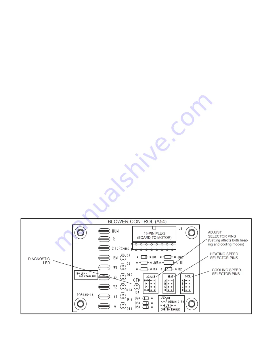
Figure 8.
COOL
The COOL jumper is used to determine the CFM during
cooling operation. This jumper selection is activated for
cooling when Y1/Y2 is energized.
The blower motor runs at 80 percent of the selected air
flow for the first 7-1/2 minutes of each cooling demand.
This feature allows for greater humidity removal and saves
energy.
In the cooling mode, the blower control delays blower
operation for 5 seconds after the compressor starts. The
blower continues to operate for 90 seconds after the
compressor is de-energized.
HEAT
The HEAT jumper is used to determine CFM during gas
heat operation only. These jumper selections are activated
only when W1/W2 is energized.
In the heating mode, the blower control delays blower
operation for 30 seconds after the flame is established.
The blower continues to operate for 90 seconds after the
gas valve is de-energized.
CONTINUOUS FAN
When the thermostat is set for “Continuous Fan” operation
and there is no demand for heating or cooling, the blower
control will provide 50 percent of the COOL CFM selected.
DEHUMIDIFICATION
The blower control includes an HUM terminal which
provides for connection of a humidistat. The JW1 resistor
on the blower control must be cut to activate the HUM
terminal. The humidistat must be wired to open on humidity
rise. When the dehumidification circuit is used, the variable
speed motor will reduce the selected air flow rate by 25
percent when humidity levels are high. An LED (D1) lights
when the blower is operating in the dehumidification mode.
Cooling System
The cooling system is a factory-charged with HFC-R-410A.
The compressor is hermetically sealed and base-mounted
with rubber-insulated bolts.
Cooling Sequence of Operation
When the thermostat calls for cooling, R is closed to Y1
(see the wiring diagrams starting on Page 21). This
action completes the low voltage control circuit, energizing
the compressor, condenser fan motor, and blower motor.
Second stage cooling is initiated by thermostat energizing
Y2.
Unit compressors have internal protection. In the event there
is an abnormal rise in the temperature of the compressor,
the protector will open and cause the compressor to stop.
Unit is equipped with drain pan overflow protection. In the
event of a restriction/blockage to the condensate disposal
system, the overflow switch will open, breaking the “R”
signal (power) to the thermostat and canceling the call for
cool/heat.
Blower Delay – Cooling
The circulating air blower includes integrated delay timing.
Timings are not adjustable. Blower “ON” delay is 5 seconds
after the compressor starts and blower “OFF” timing is 60
seconds after the compressor shuts down.
NOTE:
There is no blower OFF delay when there is a call
for G (fan only).
Cooling System Performance
This equipment is a self-contained, factory-optimized
refrigerant system. The unit should not require adjustments
to system charge when properly installed. If unit
performance is questioned, perform the following checks.


