background image

Page 35

TABLE 9 

Gas Pipe Capacity - ft3/hr (m3/hr)

Nominal 

Iron Pipe 

Size Inches 

(mm)

Internal 

Diameter 

inches 

(mm)

Length of Pipe - feet (m)

10 

(3.048)

20 

(6.096)

30 

(9,144)

40 

(12,192)

50 

(15.240)

60 

(18.288)

70 

(21.336)

80 

(24.384)

90 

(27.432)

100 

(30,480)

1/2 

(12.7)

.622 

(17.799)

172 

(4.87)

118 

(3.34)

95 

(2.69)

81 

(2.29)

72 

(2.03)

65 

(1.84)

60 

(1.69)

56 

(1.58)

52 

(1.47)

50 

(1.42)

3/4 

(19.05)

.824 

(20.930)

360 

(10.19)

247 

(7.000)

199 

(5.63)

170 

(4.81)

151 

(4.23)

137 

(3.87)

126 

(3.56)

117 

(3.31)

110 

(3.11)

104 

(2.94)

(25.4)

1.049 

(26.645)

678 

(19.19)

466 

(13.19)

374 

(10.59)

320 

(9.06)

284 

(8.04)

257 

(7.27)

237 

(6.71)

220 

(6.23)

207 

(5.86)

195 

(5.52)

1-1/4 

(31.75)

1.380 

(35.052)

1350 

(38.22)

957 

(27.09)

768 

(22.25)

657 

(18.60)

583 

(16.50)

528 

(14.95)

486 

(13.76)

452 

(12.79)

424 

(12.00)

400 

(11.33)

1-1/2 

(38.1)

1.610 

(40.894)

2090 

(59.18)

1430 

(40.49)

1150 

(32.56)

985 

(27.89)

873 

(24.72)

791 

(22.39)

728 

(20.61)

677 

(19.17)

635 

(17.98)

600 

(17.00)

(50.8)

2.067 

(52.502)

4020 

(113.83)

2760 

(78.15)

2220 

(62.86)

1900 

(53.80)

1680 

(47.57)

1520 

(43.04)

1400 

(39.64)

1300 

(36.81)

1220 

(34.55)

1160 

(32.844)

2-1/2 

(63.5)

2.469 

(67.713)

6400 

(181.22)

4400 

(124.59)

3530 

(99.95)

3020 

(85.51)

2680 

(75.88)

2480 

(70.22)

2230 

(63.14)

2080 

(58.89)

1950 

(55.22)

1840 

(52.10)

(76.2)

3.068 

(77.927)

11300 

(319.98)

7780 

(220.30)

6250 

(176.98)

5350 

(151.49)

4740 

(134.22)

4290 

(121.47)

3950 

(111.85)

3670 

(103.92)

3450 

(97.69)

3260 

(92.31)

NOTE -

 Capacity given in cubic feet (m3 ) of gas per hour and based on 0.60 specific gravity gas.

Removal of the Furnace from Common Vent

In the event that an existing furnace is removed from a 

venting system commonly run with separate gas applianc-

es, the venting system is likely to be too large to properly 

vent the remaining attached appliances.
Conduct the following test while each appliance is oper-

ating and the other appliances (which are not operating) 

remain connected to the common venting system. If the 

venting system has been installed improperly, you must 

correct the system as indicated in the general venting re-

quirements section.

 WARNING

CARBON MONOXIDE POISONING HAZARD

Failure to follow the steps outlined below for each 

appliance connected to the venting system being placed 

into operation could result in carbon monoxide poisoning 

or death.
The following steps shall be followed for each appliance 

connected to the venting system being placed into 

operation, while all other appliances connected to the 

venting system are not in operation:

1 -   Seal any unused openings in the common venting 

system.

2 - 

 Inspect  the  venting  system  for  proper  size  and 

horizontal pitch. Determine that there is no blockage, 

restriction, leakage, corrosion, or other deficiencies 

which could cause an unsafe condition.

3 -   

Close all building doors and windows and all 

doors between the space in which the appliances 

remaining connected to the common venting system 

are located and other spaces of the building. Turn on 

clothes dryers and any appliances not connected to 

the common venting system. Turn on any exhaust 

fans, such as range hoods and bathroom exhausts, 

so they will operate at maximum speed. Do not 

operate  a  summer  exhaust  fan.  Close  fireplace 

dampers.

4 -   Follow the lighting instructions. Turn on the appliance 

that is being inspected. Adjust the thermostat so 

that the appliance operates continuously.

5 -   After the main burner has operated for 5 minutes, 

test for leaks of flue gases at the draft hood relief 

opening. Use the flame of a match or candle.

6 -   After determining that each appliance connected 

to the common venting system is venting properly, 

(step 3) return all doors, widows, exhaust fans, 

fireplace  dampers,  and  any  other  gas-burning 

appliances to their previous mode of operation.

7 -   If a venting problem is found during any of the 

preceding tests, the common venting system must 

be modified to correct the problem.

Resize the common venting system to the minimum 

vent pipe size determined by using the appropriate 

tables in Appendix G. (These are in the current stan-

dards of the National Fuel Gas Code ANSI Z223.1.

Summary of Contents for ML193UH

Page 1: ...ler or equivalent service agency or the gas supplier 2018 Lennox Industries Inc Dallas Texas USA MERIT SERIIES GAS FURNACE UP FLOW HORIZONTAL AIR DISCHARGE AIR FLOW UPFLOW AIR FLOW AIR FLOW HORIZONTAL RIGHT HORIZONTAL LEFT Contents Unit Dimensions inches mm 2 ML193UH Gas Furnace 3 Shipping and Packing List 3 Safety Information 3 Use of Furnace as Construction Heater 4 General 5 Combustion Dilution...

Page 2: ... Side Return Air Filter Kit is not for use with the Optional Return Air Base 1 2 7 8 73 AIR FLOW Flue Condensate Trap Assembly Furnished for external field installation on either side of unit See installation instructions for additional information 7 178 NOTE 60C and 60D size units that require air volumes over 1800 cfm must have one of the following 1 Single side return air and Optional Return Ai...

Page 3: ...hing 1 Snap plug 1 Wire tie 1 Condensate trap 1 Condensate trap cap 1 Condensate trap clamp 1 2 diameter debris screen 1 3 4 Threaded street elbow Check equipment for shipping damage If you find any damage immediately contact the last carrier The following items may also be ordered separately 1 Thermostat 1 Propane LP changeover kit 1 Return air base kit 1 Horizontal suspension kit Safety Informat...

Page 4: ...full HEAT or COOL setting When installed this furnace must be electrically grounded according to local codes In addition in the United States installation must conform with the current National Elec tric Code ANSI NFPA No 70 The National Electric Code ANSI NFPA No 70 is available from the following ad dress National Fire Protection Association 1 Battery March Park Quincy MA 02269 In Canada all ele...

Page 5: ...ensate drain system Please consult the manufacturer of your evaporator coil for their recommendations on distance required between the heat exchanger and their drain pan Adequate space must be provided between the drain pan and the furnace heat exchanger CAUTION ML193UH unit should not be installed in areas normally subject to freezing temperatures WARNING This prodcut contains a chemical known to...

Page 6: ... door Though an area may appear to be unconfined it might be necessary to bring in outdoor air for combustion if the structure does not provide enough air by infiltration If the furnace is located in a building of tight construction with weather stripping and caulking around the windows and doors follow the procedures in the Air from Outside section Confined Space A confined space is an area with ...

Page 7: ...on Field Provided FIGURE 7 If air from outside is brought in for combustion and ventila tion the confined space must have two permanent open ings One opening shall be within 12 inches 305 mm of the top of the enclosure and one opening within 12 inches 305 mm of the bottom These openings must commu nicate directly or by ducts with the outdoors or spaces crawl or attic that freely communicate with t...

Page 8: ...th 1 3HP and 1 2HP blower motors these blower motor housings will be tagged have a rigid shipping leg equipped with a shipping bolt and flat white plastic washer The bolt and washer must be removed before the furnace is placed into operation After the bolt and washer have been removed the rigid leg will not touch the blower housing RIGID LEG Remove shipping bolt and washer Blower motor with three ...

Page 9: ...NT VIEW AIR FLOW END VIEW UNIT FRONT 1 2 max Unit must be level side to side Unit may be positioned from level to 1 2 toward the front to aid in draining FRONT VIEW SIDE VIEW 1 2 max AIR FLOW UNIT FRONT SIDE VIEW UNIT FRONT UPFLOW APPLICATION FIGURE 11 ...

Page 10: ...per clearances to accommodate condensate trap For installations on a combustible floor do not install the furnace directly on carpeting tile or other combustible materials other than wood flooring FIGURE 12 Return Air Guidelines Return air can be brought in through the bottom or either side of the furnace installed in an upflow application If the furnace is installed on a platform with bottom retu...

Page 11: ... W x H 23 x 11 in 584 x 279 mm The opening can be cut as needed to accommodate plenum or IAQ cabinet while maintaining dimensions shown Side return air openings must be cut in the field There are cutting guides stenciled on the cabinet for the side return air opening The size of the opening must not extend beyond the markings on the furnace cabinet 2 To minimize pressure drop the largest opening h...

Page 12: ...stalling the unit in a crawl space a proper support platform may be created using cement blocks 4 Route auxiliary drain line so that water draining from this outlet will be easily noticed by the homeowner The ML193UH furnace can be installed in horizontal appli cations with either right or left hand air discharge Refer to FIGURE 17 for clearances in horizontal applications Horizontal Application H...

Page 13: ...t Specifications bulletin Additional information is provided in Service and Application Note ACC002 August 2000 TABLE 1 Furnace Cabinet Width Filter Size Side Return Bottom Return 17 1 2 16 X 25 X 1 1 16 X 25 X 1 1 21 16 X 25 X 1 1 20 X 25 X 1 1 24 1 2 16 X 25 X 1 2 24 X 25 X 1 1 Duct System Use industry approved standards to size and install the supply and return air duct system Refer to ACCA Man...

Page 14: ...t Use PVC primer and solvent cement or ABS solvent ce ment meeting ASTM specifications refer to Table 2 As an alternate use all purpose cement to bond ABS PVC or CPVC pipe when using fittings and pipe made of the same materials Use transition solvent cement when bonding ABS to either PVC or CPVC Low temperature solvent cement is recommended during cooler weather Metal or plastic strapping may be u...

Page 15: ...rocedure All cementing of joints should be done according to the specifications outlined in ASTM D 2855 NOTE A sheet metal screw may be used to secure the intake pipe to the connector if desired Use a drill or self tapping screw to make a pilot hole DANGER DANGER OF EXPLOSION Fumes from PVC glue may ignite during system check Allow fumes to dissipate for at least 5 minutes before placing unit into...

Page 16: ... heat of the original furnace flue products the existing vent pipe is probably oversized for the single water heater or other appliance The vent should be checked for proper draw with the remaining appliance REPLACING FURNACE THAT WAS PART OF A COMMON VENT SYSTEM CHIMNEY OR GAS VENT Check sizing for water heater only FURNACE Replaced WATER HEATER OPENINGS To Adjacent Room FIGURE 21 CAUTION Do not ...

Page 17: ...bow must be added to the elbow count used to determine acceptable vent lengths Contact the Application Department for more information concerning sizing of vent systems which include multiple pipe sizes Horizontal Installation Offset Requirements NOTE Exhaust pipe MUST be glued to furnace exhaust fittings NOTE ward unit A minimum of 1 4 6mm drop for each 12 305mm of horizontal run is mandatory for...

Page 18: ...el 045 070 090 110 135 045 070 090 110 135 045 070 090 110 135 1 73 58 42 22 n a 105 90 64 39 n a 121 121 114 114 105 2 68 53 37 17 100 85 59 34 116 116 109 109 100 3 63 48 32 12 95 80 54 29 111 111 104 104 95 4 58 43 27 n a 90 75 49 24 106 106 99 99 90 5 53 38 22 85 70 44 19 101 101 94 94 85 6 48 33 17 80 65 39 14 96 96 89 89 80 7 43 28 12 75 60 34 n a 91 91 84 84 75 8 38 23 n a 70 55 29 86 86 79...

Page 19: ...f 2 PVC pipe possible INTAKE 2 TRANSITION 3 2 EXHAUST INTAKE FIGURE 24 FIGURE 25 TRANSITION SIDE VIEW 2 2 2 2 or TYPICAL EXHAUST AND INTAKE PIPE CONNECTIONS IN HORIZONTAL DIRECT OR NON DIRECT VENT APPLICATIONS RIGHT HAND DISCHARGE SHOWN 3 2 45 MAX 45 MAX DO NOT transition from smaller to larger pipe in horizontal runs of exhaust pipe EXHAUST 12 max 2 When transitioning up in pipe size use the shor...

Page 20: ...T VENT APPLICATIONS Horizontal Right Hand Air Discharge Application Shown INTAKE DEBRIS SCREEN Provided OR NOTE Debris screen may be positioned straight out preferred or with an elbow rotated to face down coupling PVC pipe FIGURE 27 Follow the next two steps when installing the unit in Non Direct Vent applications where combustion air is taken from indoors and flue gases are discharged outdoors 1 ...

Page 21: ...and the flue gases are discharged to the out doors The ML193UH is then classified as a direct vent Category IV gas furnace In both Non Direct Vent and Direct Vent applications the vent termination is limited by local building codes In the absence of local codes refer to the current National Fuel Gas Code ANSI Z223 1 NFPA 54 in U S A and current CSA B149 Natural Gas and Propane Installation Codes i...

Page 22: ... 2 in N A 7 N A 15 N A 22 N A N A N A 3 in N A N A N A 10 10 16 16 18 18 1Refer to 99 Minimum Design Temperature table provided in the current edition of the ASHRAE Fundamentals Handbook 2 Poly Propylene vent pipe PP by Duravent and Centrotherm NOTE Concentric terminations are the equivalent of 5 and should be considered when measuring pipe length NOTE Maximum unisulated vent lengths listed may in...

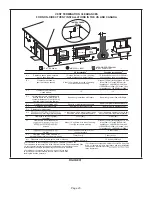
Page 23: ... located on public property Clearance under veranda porch deck or balcony 12 Equal to or greater than soffit depth 3 feet 9m 12 3 feet 9m within a height 15 feet 4 5m above the meter regulator assembly 3 feet 9m 6 inches 152mm for appliances 10 000 Btuh 3kw 12 inches 305mm for appliances 10 000 Btuh 3kw and 100 000 Btuh 30kw 36 inches 9m for appliances 100 000 Btuh 30kw 3 feet 9m above if within 1...

Page 24: ...e under veranda porch deck or balcony 12 7 feet 2 1m 3 feet 9m within a height 15 feet 4 5m above the meter regulator assembly 3 feet 9m 6 inches 152mm for appliances 10 000 pliances 10 000 Btuh 3kw and 50 000 pliances 50 000 Btuh 15kw 6 inches 152mm for appliances 10 000 Btuh 3kw 12 inches 305mm for appliances 10 000 Btuh 3kw and 100 000 Btuh 30kw 36 inches 9m for appliances 100 000 Btuh 30kw 3 f...

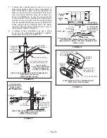
Page 25: ... venting in different pressure zones the maximum separation requirement of intake and exhaust pipe DOES NOT apply 3 On roof terminations the intake piping should terminate straight down using two 90 elbows See FIGURE 33 4 Exhaust piping must terminate straight out or up as shown A reducer may be required on the exhaust piping at the point where it exits the structure to improve the velocity of exh...

Page 26: ...t metal strap must be field installed to support the weight of the termination kit FLASHING Not Furnished CLAMP FIELD PROVIDED REDUCER MAY BE REQUIRED TO ADAPT LARGER VENT PIPE SIZE TO TERMINATION INTAKE 12 305mm FIGURE 36 12 305mm Min above grade or cumulation DIRECT VENT CONCENTRIC WALL TERMINATION 71M80 69M29 or 60L46 US 41W92 or 41W93 Canada INTAKE AIR EXHAUST AIR INTAKE AIR INTAKE AIR EXHAUST...

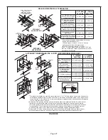
Page 27: ...m Min 12 305 mm Min 20 508 mm Max 6 152 mm Max Intake Elbow WALL SUPPORT B A D E B D E A ALTERNATE TERMINATIONS TEE FORTY FIVE DEGREE ELBOWS ONLY D C 12 1 2 E B A 1 2 As required Flue gas may be acidic and may adversely affect some building materials If a side wall vent termination is used and flue gases will impinge on the building materials a corrosion resistant shield 24 inches square should be...

Page 28: ...E AVE SNOW ACCUMULATION FIGURE 42 3 If exhaust piping must be run up a side wall to position above snow accumulation or other obstructions piping must be supported every 24 inches 610mm When exhaust piping must be run up an outside wall any reduction in exhaust pipe size must be done after the final elbow 4 Distance between exhaust pipe terminations on multiple furnaces must meet local codes NOTE ...

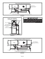
Page 29: ...yond condensate trap or trap must be re located to avoid interference Trap same on right side Plug same on left side 1 1 2 in Rubber Grommet FIGURE 44 5 FIGURE 47 and FIGURE 49 show the furnace and evaporator coil using a separate drain If necessary the condensate line from the furnace and evaporator coil can drain together See FIGURE 48 FIGURE 50 and FIGURE 51 Upflow furnace FIGURE 50 In upflow f...

Page 30: ...must slope down a minimum 1 4 per ft toward trap FIGURE 46 Furnace With Evaporator Coil Using A Separate Drain Condensate DrainConnection Field Provided Vent 1 min 2 max above condensate connection Evaporator drain line required Trap at coil is optional FIGURE 47 HorizontalFurnace4 Min to 5 Max above condensatedrain connection FurnaceCondensate DrainConnection From Evaporator Coil Optional Condens...

Page 31: ...n in horizontal left hand discharge position Condensat e Drain Connection 4 min to 5 Max above condensatedrain connection 5 max PVC Pipe Only 4 min 5 max Evaporator Coil Drain Pan Piping from furnace and evaporator coil must slope down a minimum 1 4 per ft toward trap Trap at coil is optional FIGURE 51 Furnace with Evaporator Coil Using a Separate Drain Unit shown in horizontal left hand discharge...

Page 32: ...Drain Connection In Unit Condensate Drain Connection In Unit Vent To Drain Condensate Drain Connection In Unit Optional Condensate Drain Connection OptionalDrainPipingFromTrap DrainTrapAssembly Furnished DrainTrap Assembly with 1 2 inch Piping DrainTrap Assembly with 3 4 inch Piping 1 2 inch 3 4 inch 1 25 mm Min 2 50 mm Max Above Top Of Condensate Drain Connection In Unit 1 25 mm Min 2 50 mm Max A...

Page 33: ...dumb waiters or elevator shafts Center gas line through piping hole Gas line should not touch side of unit See FIGURE 55 and FIGURE 56 4 Piping should be sloped 1 4 inch per 15 feet 6mm per 5 6m upward toward the gas meter from the furnace The piping must be supported at proper intervals every 8 to 10 feet 2 44 to 3 05m using suitable hangers or straps Install a drip leg in vertical pipe runs to s...

Page 34: ...pflow Application Left Side Piping Standard DRIP LEG MANUAL MAIN SHUT OFF VALVE GROUND JOINT UNION DRIP LEG MANUAL MAIN SHUT OFF VALVE Upflow Application Right Side Piping Alternate 1 2 NPT 1 2 NPT NOTE BLACK IRON PIPE ONLY TO BE ROUTED INSIDE OF CABINET FIGURE 55 GROUND JOINT UNION DRIP LEG MANUAL MAIN SHUT OFF VALVE GROUND JOINT UNION DRIP LEG MANUAL MAIN SHUT OFF VALVE GROUND JOINT UNION DRIP L...

Page 35: ...icated in the general venting re quirements section WARNING CARBON MONOXIDE POISONING HAZARD Failure to follow the steps outlined below for each appliance connected to the venting system being placed into operation could result in carbon monoxide poisoning or death The following steps shall be followed for each appliance connected to the venting system being placed into operation while all other a...

Page 36: ...estrictions Protected by either a fuse or circuit breaker select circuit protection and wire size according to unit nameplate CAUTION Failure to use properly sized wiring and circuit breaker may result in property damage Size wiring and circuit breaker s per Product Specifications bulletin EHB and unit rating plate NOTE Unit nameplate states maximum current draw Maximum Over Current Protection all...

Page 37: ... external relay relay Thermostat Install the room thermostat according to the instructions provided with the thermostat See figure FIGURE 58 for thermostat designations If the furnace is being matched with a heat pump refer to the FM21 installation instruction or appropriate dual fuel thermostat instructions Indoor Blower Speeds 1 When the thermostat is set to FAN ON the indoor blower will run con...

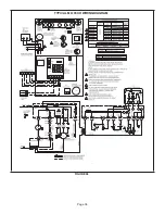
Page 38: ...Page 38 TYPICAL ML193UH WIRING DIAGRAM FIGURE 58 ...

Page 39: ... for diagnostic code recall The control stores the last 5 fault codes in non volatile memory The most recent fault code is flashed first the oldest fault code is flashed last There is a 2 second pause between codes When the push button switch is pressed for less than 5 seconds the control will flash the stored fault codes when the switch is released The fault code history may be cleared by press i...

Page 40: ...into operation 2 Set the thermostat to initiate a heating demand 3 Allow the burners to fire for approximately 3 minutes 4 Adjust the thermostat to deactivate the heating demand 5 Wait for the combustion air inducer to stop Set the thermostat to initiate a heating demand and again allow the burners to fire for approximately 3 minutes 6 Adjust the thermostat to deactivate the heating demand and wai...

Page 41: ...nace should operate at least 5 minutes before check ing gas flow Determine time in seconds for two revolu tions of gas through the meter Two revolutions assures a more accurate time Divide by two and compare to time n table 10 below If manifold pressure matches table 11 and rate is incorrect check gas orifices for proper size and restriction Remove temporary gas meter if installed NOTE To obtain a...

Page 42: ...s unit Refer to the changeover kit installation instruction for the conversion procedure TABLE 13 Manifold and Supply Line Pressure 0 10 000ft ML193 Unit Gas Manifold Pressure in wg Supply Line Pressure in w g 0 10000 ft 0 4500 ft 4501 5500 ft 5501 6500 ft 6501 7500 ft 7501 10 000 ft All Models Natural 3 5 3 3 3 2 3 1 3 5 4 5 13 0 L P Propane 10 0 9 4 9 1 8 8 10 0 11 0 13 0 NOTE A natural to L P p...

Page 43: ...sually inspect the venting system for proper size and horizontal pitch Determine there is no blockage or restriction leakage corrosion or other deficiencies which could cause an unsafe condition 3 To the extent that it is practical close all building doors and windows and all doors between the space in which the appliances connected to the venting system are located and other spaces of the buildin...

Page 44: ...erating Correct voltage is 120VAC 10 3 Check amp draw on the blower motor with blower access panel in place Motor Nameplate__________Actual__________ Blower Speeds Follow the steps below to change the blower speeds 1 Turn off electrical power to furnace 2 2 Remove blower access panel 3 Disconnect existing speed tap at integrated control speed terminal HEAT FAN OFF TIME IN SECONDS To adjust fan off...

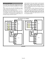
Page 45: ...terminals of the two controls The 24 VAC secondary of the two systems must be in phase All thermostat connections are made to one con trol only FIGURE 62 show wiring for two stage and single stage thermostats The twinned furnace without thermostat connections is to have the call for heat supplied by an external 24VAC isolation relay to prevent its rollout switch from being by passed by the other t...

Page 46: ... at www ahrinet org 9 Ensure sufficient combustion air is available to the furnace Fresh air grilles and louvers on the unit and in the room where the furnace is installed must be properly sized open and unobstructed to provide combustion air 10 Inspect the furnace intake and exhaust pipes to make sure they are in place structurally sound without holes blockage or leakage and the exhaust pipe is s...

Page 47: ...he existing four screws Burners are self aligning to center of clam shells 11 Reconnect ground wire 12 Reconnect flame sensor wire 13 Reconnect rollout switch wires 14 Reconnect ignitor wires 15 Reconnect gas valve wires 16 Reconnect gas supply line to gas valve 17 Refer to instructions on verifying gas and electrical connections when re establishing supplies 18 Follow instructions to place furnac...

Page 48: ...Installed Properly Pipes Supported Condensate Trap Primed Line Sloped Heat Cable Installed and Operable if applicable 2 2 2 1 Horizontal Pipes Sloped if applicable UNIT SET UP 3 4 Flter RETURN AIR Furnace Model Number_______________ Serial Number_________________ 3 DUCT SYSTEM SUPPLY AIR DUCT Sealed Insulated if necessary RETURN DUCT Sealed Filter Installed and Clean Grilles Unobstructed 4 VOLTAGE...

Page 49: ...ATIC 5 Supply External Static _______ Return External Static ______ Total External Static _______ CONDENSATE LINE 6 Leak Free VENT PIPE 7 Leak Free COOLING MODE INDOOR BLOWER AMPS______ 3 TEMPERATURE DROP Return Duct Temperature _________ Supply Duct Temperature _ _______ Temperature Drop _________ 4 DRAIN LINE 8 Leak Free THERMOSTAT Adjusted and Programmed Explained Operation to Owner 9 SUPPLY AI...

Page 50: ... eight 8 feet above grade directly in line with the exhaust vent terminal for the horizontally vented gas fueled heating appliance or equipment The sign shall read in print size no less than one half 1 2 inch in size GAS VENT DIRECTLY BELOW KEEP CLEAR OF ALL OBSTRUCTIONS 4 INSPECTION The state or local gas inspector of the side wall horizontally vented gas fueled equipment shall not approve the in...

Page 51: ...nce of Saskatchewan and Manitoba Lennox approves the following termination for use in Saskatchewan and Manitoba Canada C 12 D B A 2 51MM Vent Pipe 3 76MM Vent Pipe 12 305 mm Min 12 305 mm Min 6 152 mm Min 24 610 mm Max 6 152 mm Max 6 152 mm Min 24 610 mm Max 6 152 mm Max A Clearance above grade or average snow accumulation B Horizontal separation between intake and exhaust C Exhaust pipe length D ...

Reviews: