Page 22
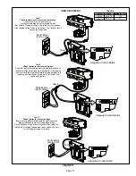
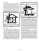
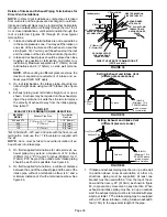
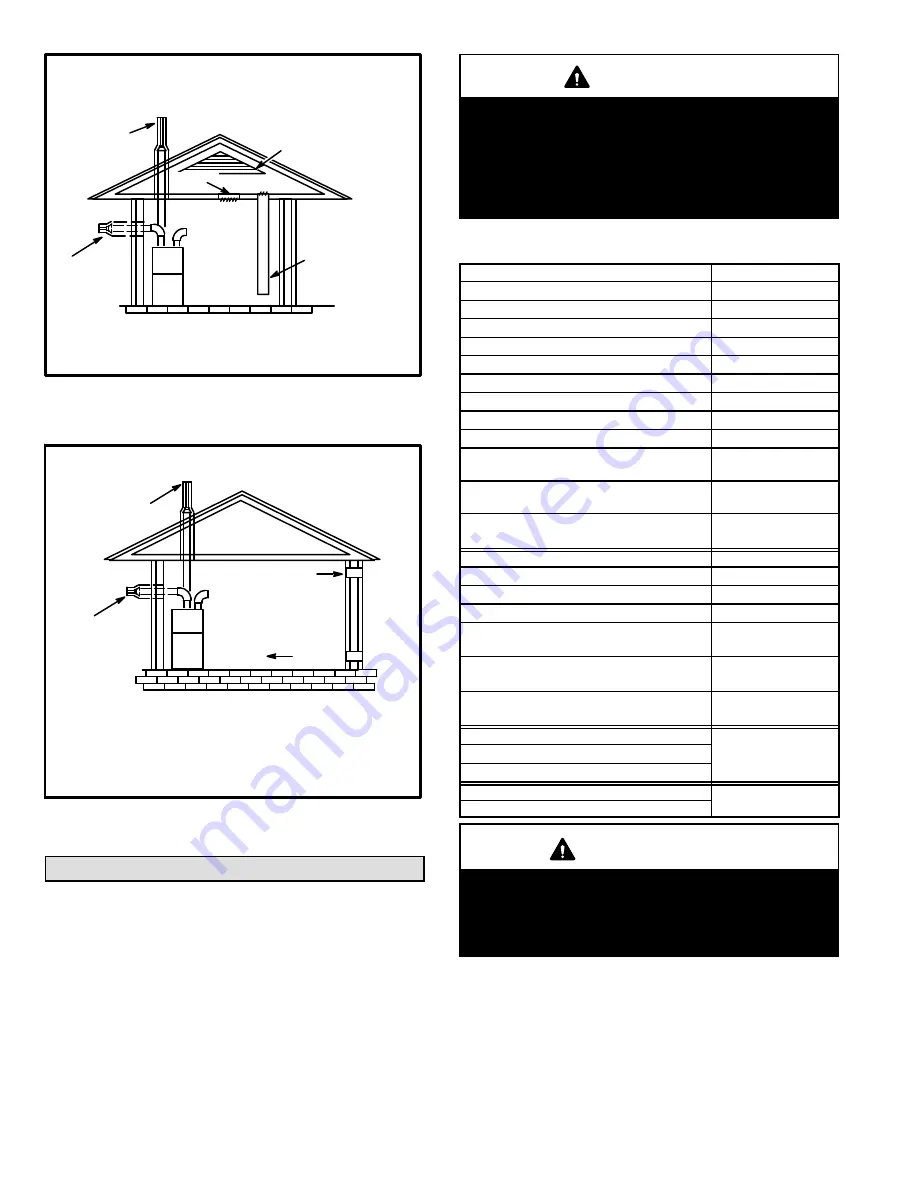
FIGURE 21
EQUIPMENT IN CONFINED SPACE - ALL AIR FROM OUTSIDE
(All Air Through Ventilated Attic)
NOTE
-The inlet and outlet air openings shall each have a free area of
at least one square inch per 4,000 Btu (645mm
2
per 1.17kW) per hour
of the total input rating of all equipment in the enclosure.
OUTLET
AIR
VENTILATION LOUVERS
(Each end of attic)
INLET AIR
(Ends 12” above
bottom)
ROOF TERMINATED
EXHAUST PIPE
SIDE WALL
TERMINATED
EXHAUST PIPE
(ALTERNATE
LOCATION)
FURNACE
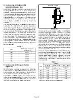
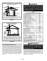
FIGURE 22
EQUIPMENT IN CONFINED SPACE -
ALL AIR FROM OUTSIDE
OUTLET AIR
INLET AIR
NOTE
-Each air duct opening shall have a free area of at least one
square inch per 2,000 Btu (645mm
2
per .59kW) per hour of the total
input rating of all equipment in the enclosure. If the equipment room
is located against an outside wall and the air openings communi
cate directly with the outdoors, each opening shall have a free area
of at least 1 square inch per 4,000 Btu (645mm
2
per 1.17kW) per
hour of the total input rating of all other equipment in the enclosure.
ROOF TERMINATED
EXHAUST PIPE
SIDE WALL
TERMINATED
EXHAUST PIPE
(ALTERNATE
LOCATION)
FURNACE
Pipe & Fittings Specifications
All pipe, fittings, primer and solvent cement must conform
with American National Standard Institute and the Ameri
can Society for Testing and Materials (ANSI/ASTM) stan
dards. The solvent shall be free flowing and contain no
lumps, undissolved particles or any foreign matter that ad
versely affects the joint strength or chemical resistance of
the cement. The cement shall show no gelation, stratifica
tion, or separation that cannot be removed by stirring. Re
fer to the table 11 below for approved piping and fitting ma
terials.
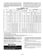
CAUTION
Solvent cements for plastic pipe are flammable liq
uids and should be kept away from all sources of
ignition. Do not use excessive amounts of solvent
cement when making joints. Good ventilation should
be maintained to reduce fire hazard and to minimize
breathing of solvent vapors. Avoid contact of ce
ment with skin and eyes.
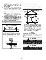
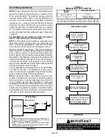
TABLE 11
PIPING AND FITTINGS SPECIFICATIONS
Schedule 40 PVC (Pipe)
D1785
Schedule 40 PVC (Cellular Core Pipe)
F891
Schedule 40 PVC (Fittings)
D2466
Schedule 40 CPVC (Pipe)
F441
Schedule 40 CPVC (Fittings)
F438
SDR-21 PVC or SDR-26 PVC (Pipe)
D2241
SDR-21 CPVC or SDR-26 CPVC (Pipe)
F442
Schedule 40 ABS Cellular Core DWV (Pipe)
F628
Schedule 40 ABS (Pipe)
D1527
Schedule 40 ABS (Fittings)
D2468
ABS-DWV (Drain Waste & Vent)
(Pipe & Fittings)
D2661
PVC-DWV (Drain Waste & Vent)
Pipe & Fittings)
D2665
PRIMER & SOLVENT CEMENT
ASTM
SPECIFICATION
PVC & CPVC Primer
F656
PVC Solvent Cement
D2564
CPVC Solvent Cement
F493
ABS Solvent Cement
D2235
PVC/CPVC/ABS All Purpose Cement For
Fittings & Pipe of the same material
D2564, D2235, F493
ABS to PVC or CPVC Transition Solvent
Cement
D3138
CANADA PIPE & FITTING & SOLVENT
CEMENT
MARKING
PVC & CPVC Pipe and Fittings
ULCS636
PVC & CPVC Solvent Cement
ABS to PVC or CPVC Transition Cement
POLYPROPYLENE VENTING SYSTEM
ULC-S636
PolyPro by Duravent
IMPORTANT
ML195UH exhaust and intake connections are made
of PVC. Use PVC primer and solvent cement when
using PVC vent pipe. When using ABS vent pipe, use
transitional solvent cement to make connections to
the PVC fittings in the unit.
Use PVC primer and solvent cement or ABS solvent ce
ment meeting ASTM specifications, refer to Table 11. As
an alternate, use all purpose cement, to bond ABS, PVC, or
CPVC pipe when using fittings and pipe made of the same
materials. Use transition solvent cement when bonding
ABS to either PVC or CPVC.


