background image

Page 24

 7 - If a venting problem is found during any of the preced­

ing tests, the common venting system must be modi­
fied to correct the problem.

Resize the common venting system to the minimum

vent pipe size determined by using the appropriate
tables in Appendix G. (These are in the current stan­
dards of the National Fuel Gas Code ANSI Z223.1.

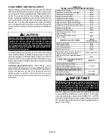
CHIMNEY

OR GAS

VENT

(Check sizing

for water

heater only)

FURNACE

(Replaced
by EL296)

WATER

HEATER

OPENINGS

(To Adjacent

Room)

If an ML296UHV furnace replaces a furnace which was
commonly vented with another gas appliance, the size of
the existing vent pipe for that gas appliance must be
checked. Without the heat of the original furnace flue prod­
ucts, the existing vent pipe is probably oversized for the
single water heater or other appliance. The vent should be
checked for proper draw with the remaining appliance.

FIGURE 16

REPLACING FURNACE THAT

WAS PART OF A COMMON

VENT SYSTEM

Exhaust Piping (Figures 17, 19 and 20)

Route piping to outside of structure. Continue with installa­
tion following instructions given in piping termination sec­
tion.

CAUTION

Do not discharge exhaust into an existing stack or
stack that also serves another gas appliance. If verti­
cal discharge through an existing unused stack is re­
quired, insert PVC pipe inside the stack until the end
is even with the top or outlet end of the metal stack.

CAUTION

The exhaust vent pipe operates under positive pres­
sure and must be completely sealed to prevent leak­
age of combustion products into the living space.

Vent Piping Guidelines

NOTE - 

Lennox has approved the use of DuraVent

® 

and

Centrotherm manufactured vent pipe and terminations as
an option to PVC. When using the PolyPro

®

 by DuraVent or

InnoFlue

®

 by Centrotherm venting system the vent pipe re­

quirements stated in the unit installation instruction – min­
imum & maximum vent lengths, termination clearances,
etc. – apply and must be followed. Follow the instructions
provided with


PoyPro by DuraVent and InnoFlue by Cen­

trotherm venting system for assembly or if requirements
are more restrictive. The PolyPro by Duravent and In­
noFlue by Centrotherm venting system must also follow
the uninsulated and unconditioned space criteria listed in
table 16.

The ML296UHV can be installed as either a Non-Direct
Vent or a Direct Vent gas central furnace.

NOTE

 - In Non‐Direct Vent installations, combustion air is

taken from indoors or ventilated attic or crawlspace and flue
gases are discharged outdoors. In Direct Vent installations,
combustion air is taken from outdoors and flue gases are
discharged outdoors.

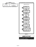
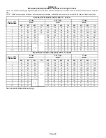
Intake and exhaust pipe sizing --

 Size pipe according to

tables 13 and 

14

. Count all elbows inside and outside the

home. Table 13 lists the 

minimum

 vent pipe lengths per­

mitted. Table 

14

 lists the 

maximum

 pipe lengths permitted.

Regardless of the diameter of pipe used, the standard roof
and wall terminations described in section 

Exhaust Piping

Terminations

 should be used. Exhaust vent termination

pipe is sized to optimize the velocity of the exhaust gas as
it exits the termination. Refer to table 17.

In some applications which permit the use of several differ­
ent sizes of vent pipe, a combination vent pipe may be
used. Contact Lennox' Application Department for assis­
tance in sizing vent pipe in these applications.

NOTE 

- The exhaust collar on all models is sized to ac­

commodate 2” Schedule 40 vent pipe. In horizontal ap­
plications, any transition to exhaust pipe larger than 2”
must be made in vertical runs of the pipe. Therefore a 2”
elbow must be added before the pipe is transitioned to
any size larger than 2”. This elbow must be added to the
elbow count used to determine acceptable vent lengths.
Contact the Application Department for more information
concerning sizing of vent systems which include multiple
pipe sizes.

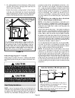
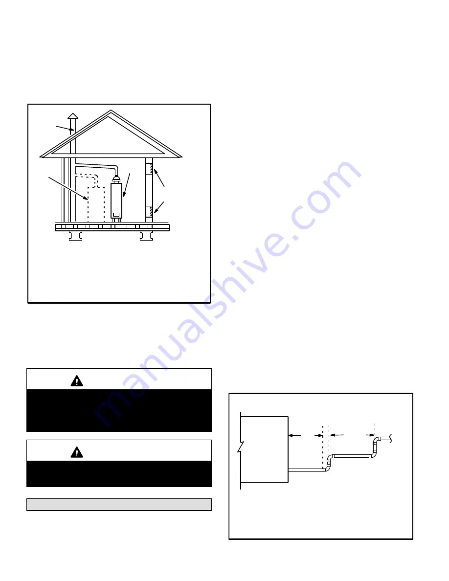
FIGURE 17

Horizontal Installation Offset Requirements

NOTE

 - Exhaust pipe MUST be glued to furnace exhaust fittings.

NOTE -

 All horizontal runs of exhaust pipe must slope back to­

ward unit. A minimum of 1/4” (6mm) drop for each 12” (305mm)
of horizontal run is mandatory for drainage.

NOTE 

- Exhaust piping should be checked carefully to make

sure there are no sags or low spots.

Exhaust Pipe

Horizontal

Gas Furnace

12” Min.

12” Max.

Summary of Contents for ML296UH045XV36B

Page 1: ...utlined in this manual are presented as a recom mendation only and do not supersede or replace local or state codes In the absence of local or state codes the guidelines and procedures outlined in this manual except where noted are recommendations only and do not consti tute code TABLE OF CONTENTS Specifications Page 2 Blower Data Page 3 I Unit Components Page 9 II Installation Page 21 III Start U...

Page 2: ...res and according to FTC labeling regulations Isolated combustion system rating for non weatherized furnaces Gas Heating Performance Model No ML296UH090XV48C ML296UH110XV60C AHRI Reference No N A N A 1 AFUE 96 96 High Fire Input Btuh 88 000 110 000 Output Btuh 84 000 106 000 Temperature rise range F 45 75 45 75 Gas Manifold Pressure in w g Nat Gas LPG Propane 3 5 10 0 3 5 10 0 Low Fire Input Btuh ...

Page 3: ...osition minimum 500 cfm Lennox Harmony III Zoning System Applications Minimum blower speed is 453 cfm BLOWER DATA ML296UH045XV36B BLOWER PERFORMANCE less filter SINGLE SIDE RETURN AIR 0 through 0 8 in w g Heating and 0 through 1 0 in w g Cooling External Static Pressure Range ADJUST Switch Positions Speed Switch Positions Second Stage HEAT Speed cfm Second Stage COOL Speed cfm D 1 C B A D C B 1 A ...

Page 4: ...sition minimum 500 cfm Lennox Harmony III Zoning System Applications Minimum blower speed is 453 cfm BLOWER DATA ML296UH070XV36B BLOWER PERFORMANCE less filter BOTTOM RETURN AIR 0 through 0 8 in w g Heating and 0 through 1 0 in w g Cooling External Static Pressure Range ADJUST Switch Positions Speed Switch Positions Second Stage HEAT Speed cfm Second Stage COOL Speed cfm D 1 C B A D C B 1 A 965 11...

Page 5: ...minimum 500 cfm Lennox Harmony III Zoning System Applications Minimum blower speed is 453 cfm BLOWER DATA ML296UH070XV36B BLOWER PERFORMANCE less filter SIDE RETURN AIR WITH OPTIONAL RETURN AIR BASE 0 through 0 8 in w g Heating and 0 through 1 0 in w g Cooling External Static Pressure Range ADJUST Switch Positions Speed Switch Positions Second Stage HEAT Speed cfm Second Stage COOL Speed cfm D 1 C...

Page 6: ...the same second stage COOL speed position minimum 500 cfm Lennox Harmony III Zoning System Applications Minimum blower speed is 453 cfm BLOWER DATA ML296UH090XV48C BLOWER PERFORMANCE less filter SINGLE SIDE RETURN AIR 0 through 0 8 in w g Heating and 0 through 1 0 in w g Cooling External Static Pressure Range ADJUST Switch Positions Speed Switch Positions Second Stage HEAT Speed cfm Second Stage C...

Page 7: ...Applications Minimum blower speed is 478 cfm BLOWER DATA ML296UH110XV60C BLOWER PERFORMANCE less filter SINGLE SIDE RETURN AIR Air volumes in bold over 1800 cfm require Optional Return Air Base and field fabricated transition to accommodate 20 x 25 x 1 in air filter in order to maintain proper air velocity 0 through 0 8 in w g Heating and 0 through 1 0 in w g Cooling External Static Pressure Range...

Page 8: ...ON Burner Box Assembly Gas Valve Heat Exchanger Combustion Air Inducer Pressure Switch Assembly Primary Limit Variable Speed Motor Two Stage Integrated Control Access Panel Bag Assemblies shipping location Field Make Up Box Door Interlock Switch ...

Page 9: ...ustion air inducer gas valve and indoor blower are controlled in response to various system inputs such as thermostat signal pressure and limit switch signal and flame signal The furnace has a built in self diagnostic capability If a system problem occurs a fault code is shown by a red LED on the control The control continuously monitors its own operation and the operation of the system If a failu...

Page 10: ...on 1 Gas Valve Second Stage 2 Second Stage Prove Switch 3 Rollout Switch In 4 Ground 5 24V Hot 6 Primary Limit In 7 Gas Valve First Stage 8 Gas Valve Common 9 24V Neutral 10 Ground 11 Rollout Switch Out 12 First Stage Prove Switch Heating Mode These units are factory set to run at the middle of the heating rise range as shown on the unit rating plate If higher or lower rise is desired reposition t...

Page 11: ...ransformer 120VAC Cont Continuous blower EAC Indoor Air Accessory 120VAC Cool Cool Speed 120VAC Park 1 Dead terminal for alternate speed tap Park 2 Dead terminal for alternate speed tap HI Heat High heat speed LO Heat Low heat speed Heat Stage Jumper single stage shown Heat Taps Cool Taps Air Flow Jumper ...

Page 12: ...igure 6 shows the location of the 16X4W and table 5 the LED codes FIGURE 5 GenTeq BLOWER MOTOR B3 MOTOR CONTROLLER J49 J48 NIDEC BLOWER MOTOR B3 FIGURE 6 MOTOR CONTROLLER 16X4W J48 J49 BLOWER MOTOR COMPONENTS FIGURE 7 STATOR WINDINGS OUTPUT SHAFT BEARING ROTOR The controller uses sensing devices to sense what position the rotor is in at any given time By sensing the position of the rotor and then ...

Page 13: ...nect switch is bounced when the disconnect is closed the dis connect contacts may become welded Try not to bounce the disconnect switch when applying power to the unit Motor Start Up When B3 begins start up the motor gently vibrates back and forth for a moment This is normal During this time the elec tronic controller is determining the exact position of the rotor Once the motor begins turning the...

Page 14: ...ed on 5 ton 1 hp units The choke is lo cated on the blower housing and is used to suppress transient current spikes Precautions If the furnace or its electronically controlled blower motor is im properly or inadequately grounded it may cause television in terference commonly known as RFI or radio frequency inter ference This interference is caused by internal switching fre quencies of the motor co...

Page 15: ...to motor windings O volts 325VDC One revolution O volts 325VDC O volts 325VDC WINDING 1 WINDING 2 WINDING 3 O volts 325VDC O volts 325VDC O volts 325VDC ÇÇÇÇÇÇÇÇÇÇÇÇÇÇÇÇÇÇ ÇÇÇÇÇÇÇÇÇÇÇÇÇÇÇÇÇÇ ÇÇÇÇÇÇÇÇÇÇÇÇÇÇÇÇÇÇ ÇÇÇÇÇÇÇÇÇÇÇÇÇÇÇÇÇÇ ÇÇÇÇÇÇÇÇÇÇÇÇÇÇÇÇÇÇ ÇÇÇÇÇÇÇÇÇÇÇÇÇÇÇÇÇÇ WINDING 1 WINDING 2 WINDING 3 O volts 325VDC O volts 325VDC O volts 325VDC Motor speed is determined by the size of the electrical pu...

Page 16: ...ts are available from Lennox Kits include burner orifices and a gas valve 4 Flame Rollout Switches S47 Flame rollout switch is a high temperature limit located on top of the burner box one on each side See figure 11 The limit is a N C SPST manual reset limit When S47 senses rollout the circuit breaks and the ignition control immedi ately stops ignition and closes the gas valve Rollout can be cause...

Page 17: ...Page 17 ML296UHV HEATING COMPONENTS FIGURE 11 Intake Air Top Cap Sensor Rollout Switch Rollout Switch Burner Assembly Ignitor Manifold And Gas Orifices Two Stage Gas Valve Burner Box Cover ...

Page 18: ... of ignitor at the plug Reading should be between 39 and 70 ohms If the reading is correct then the problem is with the wiring between the jack plug and the control If reading is not correct the issue is the ignitor Test 3 Check ignitor for correct voltage Insert meter probes into terminals 1 and 5 use small diameter probes in order not to damage plug Check voltage during 20 second ignitor warm up...

Page 19: ... 040 8 Combustion Air Inducer Pressure Switch S18 ML296UHV X series units are equipped with a dual com bustion air pressure switch first and second stage located on the combustion air inducer orifice bracket See figure 13 The switch is connected to the combustion air inducer hous ing by means of a flexible silicone hose It monitors negative air pressure in the combustion air inducer housing The sw...

Page 20: ...and tee into the tubing from the negative side of the cold end header box and the other side of the 2 square tub ing Connect the other end of the 10 square tubing the the negative side of the measuring device 5 Operate unit and observe manometer reading Readings will change as heat exchanger warms a Take one reading immediately after start up b Take a second reading after unit has reached steady s...

Page 21: ... In addition the first three feet of vent pipe from the furnace flue collar must be accessible for inspection TABLE 11 PIPING AND FITTINGS SPECIFICATIONS Schedule 40 PVC Pipe D1785 Schedule 40 PVC Cellular Core Pipe F891 Schedule 40 PVC Fittings D2466 Schedule 40 CPVC Pipe F441 Schedule 40 CPVC Fittings F438 SDR 21 PVC or SDR 26 PVC Pipe D2241 SDR 21 CPVC or SDR 26 CPVC Pipe F442 Schedule 40 ABS C...

Page 22: ...PVC glue may ignite during system check Allow fumes to dissipate for at least 5 minutes before placing unit into operation 1 Measure and cut vent pipe to desired length 2 Debur and chamfer end of pipe removing any ridges or rough edges If end is not chamfered edge of pipe may remove cement from fitting socket and result in a leaking joint NOTE Check the inside of vent pipe thoroughly for any obstr...

Page 23: ...Failure to follow the steps outlined below for each appliance connected to the venting system being placed into operation could result in carbon mon oxide poisoning or death The following steps shall be followed for each ap pliance connected to the venting system being placed into operation while all other appliances connected to the venting system are not in operation 1 Seal any unused openings i...

Page 24: ...em for assembly or if requirements are more restrictive The PolyPro by Duravent and In noFlue by Centrotherm venting system must also follow the uninsulated and unconditioned space criteria listed in table 16 The ML296UHV can be installed as either a Non Direct Vent or a Direct Vent gas central furnace NOTE In Non Direct Vent installations combustion air is taken from indoors or ventilated attic o...

Page 25: ...ing used Standard or concentric See table 12 Which needs most elbows Intake or exhaust How many elbows Count all elbows inside and outside house Desired pipe size 2 2 1 2 3 Use table 14 or 15 to find max intake or exhaust pipe length Includes all vent pipe and elbows inside and outside the house What is the altitude of the furnace installation 7 What is the furnace capacity 045 070 090 110 IMPORTA...

Page 26: ...128 127 108 108 4 66 51 29 n a 100 100 78 43 123 122 103 103 5 61 46 24 95 95 73 38 118 117 98 98 6 56 41 19 90 90 68 33 113 112 93 93 7 51 36 14 85 85 63 28 108 107 88 88 8 46 31 n a 80 80 58 23 103 102 83 83 9 41 26 75 75 53 18 98 97 78 78 10 36 21 70 70 48 13 93 92 73 73 Standard Termination Elevation 4500 10 000 ft Number Of 90 Elbows Used 2 Pipe 2 1 2 Pipe 3 Pipe Model Model Model 045 070 090...

Page 27: ... 106 106 99 99 5 53 38 22 85 85 69 34 101 101 94 94 6 48 33 17 80 80 64 29 96 96 89 89 7 43 28 12 75 75 59 24 91 91 84 84 8 38 23 n a 70 70 54 19 86 86 79 79 9 33 18 65 65 49 14 81 81 74 74 10 28 13 60 60 44 n a 76 76 69 69 Concentric Termination Elevation 4501 10 000 ft Number Of 90 Elbows Used 2 Pipe 2 1 2 Pipe 3 Pipe Model Model Model 045 070 090 110 045 070 090 110 045 070 090 110 1 73 58 42 n...

Page 28: ...3 118 117 98 98 2 66 51 29 9 95 95 73 38 113 112 93 93 3 61 46 24 4 90 90 68 33 108 107 88 88 4 56 41 19 n a 85 85 63 28 103 102 83 83 5 51 36 14 80 80 58 23 98 97 78 78 6 46 31 9 85 75 63 18 93 92 73 73 7 41 26 4 70 70 48 13 88 87 68 68 8 36 21 n a 65 65 43 8 83 82 63 63 9 31 16 60 60 38 3 78 77 58 58 10 26 11 55 55 33 n a 73 72 53 53 Standard Termination Elevation 4500 10 000 ft Number Of 90 Elb...

Page 29: ...t length of 2 PVC pipe possible INTAKE 2 TRANSITION 3 2 EXHAUST INTAKE FIGURE 20 TRANSITION SIDE VIEW 2 2 2 2 or TYPICAL EXHAUST AND INTAKE PIPE CONNECTIONS IN HORIZONTAL DIRECT OR NON DIRECT VENT APPLICATIONS RIGHT HAND DISCHARGE SHOWN 3 2 45 MAX 45 MAX DO NOT transition from smaller to larger pipe in horizontal runs of exhaust pipe EXHAUST 12 max 2 When transitioning up in pipe size use the shor...

Page 30: ...KE PIPE CONNECTIONS HORIZONTAL NON DIRECT VENT APPLICATIONS Horizontal Right Hand Air Discharge Application Shown INTAKE DEBRIS SCREEN Provided OR NOTE Debris screen may be positioned straight out preferred or with an elbow rotated to face down coupling PVC pipe Follow the next two steps when installing the unit in Non Direct Vent applications where combustion air is taken from indoors or ventilat...

Page 31: ...rect Vent applications combustion air is taken from outdoors and the flue gases are discharged to the out doors The ML296UHV is then classified as a direct vent Category IV gas furnace In both Non Direct Vent and Direct Vent applications the vent termination is limited by local building codes In the absence of local codes refer to the current National Fuel Gas Code ANSI Z223 1 NFPA 54 in U S A and...

Page 32: ...12 N A 3 in N A N A N A N A 8 8 7 7 1Refer to 99 Minimum Design Temperature table provided in the current edition of the ASHRAE Fundamentals Handbook 2 Poly Propylene vent pipe PP by Duravent and Centrotherm NOTE Concentric terminations are the equivalent of 5 and should be considered when measuring pipe length NOTE Maximum uninsulated vent lengths listed may include the termination vent pipe exte...

Page 33: ...y inlet Clearance above paved sidewalk or paved driveway located on public property Clearance under veranda porch deck or balcony 12 Equal to or greater than soffit depth 3 feet 9m 12 3 feet 9m within a height 15 feet 4 5m above the meter regulator assembly 3 feet 9m 6 inches 152mm for appliances 10 000 Btuh 3kw 12 inches 305mm for appliances 10 000 Btuh 3kw and 100 000 Btuh 30kw 36 inches 9m for ...

Page 34: ...ove paved sidewalk or paved driveway located on public property Clearance under veranda porch deck or balcony 12 7 feet 2 1m 3 feet 9m within a height 15 feet 4 5m above the meter regulator assembly 3 feet 9m 6 inches 152mm for appliances 10 000 Btuh 3kw 9 inches 228mm for ap pliances 10 000 Btuh 3kw and 50 000 Btuh 15 kw 12 inches 305mm for ap pliances 50 000 Btuh 15kw 6 inches 152mm for applianc...

Page 35: ... in different pressure zones the maximum separation requirement of intake and ex haust pipe DOES NOT apply 3 On roof terminations the intake piping should termi nate straight down using two 90 elbows See figure 28 4 Exhaust piping must terminate straight out or up as shown A reducer may be required on the exhaust pip ing at the point where it exits the structure to improve the velocity of exhaust ...

Page 36: ... FLASHING Not Furnished CLAMP FIELD PROVIDED REDUCER MAY BE REQUIRED TO ADAPT LARGER VENT PIPE SIZE TO TERMINATION 1 1 2 38mm accelerator provided on 71M80 44W92 kits for ML296UHV045P24B 070P24B 070P36B 12 305mm INTAKE AIR EXHAUST VENT 12 305mm Min above grade or average snow accumulation FIGURE 33 DIRECT VENT CONCENTRIC WALL TERMINATION 71M80 69M29 or 60L46 US 44W92 or 44W93 Canada INTAKE AIR INT...

Page 37: ...m Min 12 305 mm Min 20 508 mm Max 6 152 mm Max Intake Elbow WALL SUPPORT B A D E B D E A ALTERNATE TERMINATIONS TEE FORTY FIVE DEGREE ELBOWS ONLY D C 12 1 2 E B A 1 2 As required Flue gas may be acidic and may adversely affect some building materials If a side wall vent termination is used and flue gases will impinge on the building materials a corrosion resistant shield 24 inches square should be...

Page 38: ...ng must be run up an outside wall any reduction in exhaust pipe size must be done after the final elbow 4 Distance between exhaust pipe terminations on mul tiple furnaces must meet local codes Crawl Space and Extended Horizontal Venting Lennox provides kit 51W18 to install 2 or 3 PVC exhaust piping through the floor joists and into the the crawl space See figure 39 This kit can also be used as a s...

Page 39: ...condensate line to an open drain Condensate line must maintain a 1 4 downward slope from the furnace to the drain 5 Figures 43 and 44 show the furnace and evaporator coil using a separate drain If necessary the conden sate line from the furnace and evaporator coil can drain together See figures 45 46 and 47 Upflow furnace figure 46 In upflow furnace applica tions the field provided vent must be a ...

Page 40: ... possible a heat cable kit may be used on the condensate trap and line Heating cable kit is available from Lennox in various lengths 6 ft 1 8m kit no 26K68 24 ft 7 3m kit no 26K69 and 50 ft 15 2m kit no 26K70 FIGURE 43 ML296UHV With Evaporator Coil Using A Separate Drain Condensate DrainConnection Field Provided Vent 1 min 2 max above condensate connection Evaporator drain line required Trap at co...

Page 41: ...densatedrain connection Condensate DrainConnection Evaporator drain line required Trap at coil is optional FIGURE 47 ML296UHV with Evaporator Coil Using a Common Drain Unit shown in horizontal left hand discharge position Condensat e Drain Connection 4 min to 5 Max above condensatedrain connection 5 max PVC Pipe Only 4 min 5 max Evaporator Coil Drain Pan Piping from furnace and evaporator coil mus...

Page 42: ...Drain Connection In Unit Condensate Drain Connection In Unit Vent To Drain Condensate Drain Connection In Unit Optional Condensate Drain Connection OptionalDrainPipingFromTrap DrainTrapAssembly Furnished DrainTrap Assembly with 1 2 inch Piping DrainTrap Assembly with 3 4 inch Piping 1 2 inch 3 4 inch 1 25 mm Min 2 50 mm Max Above Top Of Condensate Drain Connection In Unit 1 25 mm Min 2 50 mm Max A...

Page 43: ...d with suffi cient water to ensure proper condensate drain opera tion WARNING If you do not follow these instructions exactly a fire or explosion may result causing property damage personal injury or death Gas Valve Operation Figure 49 1 STOP Read the safety information at the beginning of this section 2 Set the thermostat to the lowest setting 3 Turn off all electrical power to the unit 4 This fu...

Page 44: ...the supply pressure See figure 49 Back out the 3 32 hex screw one turn connect a piece of 5 16 tubing and connect to a manometer to measure supply pressure See table 21 for supply line pressure E Check Manifold Pressure NOTE Pressure test adapter kit 10L34 is available from Lennox to facilitate manifold pressure measurement A manifold pressure post located on the gas valve provides access to the m...

Page 45: ...ensure proper operation at higher altitudes See table 20 for gas conver sion and pressure switch kits See table 21 for manifold pressures TABLE 20 LP Propane Conversion Kit and Pressure Switch Requirements at Varying Altitudes ML296 Unit Natural to LP Propane High Altitude Natural Burner Orifice Kit High Altitude LP Propane Burner Orifice Kit High Altitude Pressure Switch 0 7500 ft 0 2286m 7501 10...

Page 46: ...r or partial ground Compare the readings to the table below If the read ings exceed the maximum shown in table 1 make re pairs before operating the furnace 2 In addition measure the AC voltage from Line Hot to Line Neutral spade terminals on the integrated con trol See figure 51 This voltage should be in the range of 97 to 132 Vac TABLE 22 Furnace Status Measurement VAC Expected Maximum Power On F...

Page 47: ...ide of the system On ducted sys tems connect the other end of manometer to the return duct as above 3 With only the blower motor running and the evaporator coil dry observe the manometer reading Adjust blow er motor speed to deliver the air desired according to the job requirements For heating speed second stage heat speed external static pressure drop must not be more than 0 8 W C For cooling spe...

Page 48: ...an out cap from the condensate trap and empty water Inspect the trap then reinstall the clean out cap Condensate Hose Screen Figure 54 Check the condensate hose screen for blockage and clean if necessary 1 Turn off power to the unit 2 Remove hose from cold end header box Twist and pull screen to remove 3 Inspect screen and rinse with tap water if needed 4 Reinstall screen and turn on power to unit...

Page 49: ...witch wires 39 Reconnect sensor wire and reconnect 2 pin plug from ignitor 40 Reinstall gas valve manifold assembly Reconnect gas supply line to gas valve 41 Reconnect the combustion air intake pipe 42 Reinstall burner box cover 43 Reconnect wires to gas valve 44 Replace the blower compartment access panel 45 Reconnect gas supply piping Turn on power and gas supply to unit 46 Follow lighting instr...

Page 50: ...Page 50 VII Wiring and Sequence of Operation ...

Page 51: ...l the limits are closed Fan On When the thermostat is set for continuous fan operation and there is no demand for heating or cooling a call for fan closes the R to G circuit and the circulating blower motor runs at50 of the selected cooling CFM until switched off When the call for fan is turned off the control de energizes the circulating blower Cooling The unit is set up at the factory for single...

Reviews: