Page 5
on carpeting, tile or other combustible material other than
wood flooring. When installed on wood flooring, the addi-
tive base must be used. See Unit Dimension illustration.
Unit must be adjusted to obtain a temperature rise within
the range listed in table 4 in the Adjustments" section.
When used in conjunction with a evaporator coil, the fur-
nace shall be installed in parallel with or on the upstream
side of the evaporator coil. In a parallel flow arrangement,
the dampers or means to control flow of air shall be ade-
quate to prevent chilled air from entering the furnace, and if
manually operated, must be equipped with means to pre-
vent operation of either unit unless dampers are in the full
heat or full cool position.
When installed, furnace must be electrically grounded in
accordance with local codes or, in the absence of local
codes, with the current National Electric Code, ANSI/NFPA
No. 70, if an external electrical source is utilized.
Field wiring connection with unit must meet or exceed
specifications of type T wire and withstand a 63
F (17
C)
temperature rise.
Installation
When installed, OHR23 furnaces must be level. If the fur-
nace is not level, place fireproof wedges or shims between
the low side of the furnace and floor. Make sure the weight
of the furnace is evenly distributed on all four corners.
Strain on sides of the cabinet causing cracking and pop-
ping noises may occur if weight of furnace is not evenly dis-
tributed.
Set the unit in desired location keeping in mind the clear-
ances list in tables 2 and 3. Also keep in mind oil supply
connections, electrical supply, flue connections and suffi-
cient clearance for installing and servicing unit.
OHR23 series units may be installed in a crawl space under
a house, utility room or in a wide variety of suspended ap-
plications.
A−Horizontal Application
The OHR23 furnace is shipped from the factory in the hori-
zontal left hand air discharge application. Air flow may be
reversed to right side discharge or unit may be used as
downflow.
Reversing Airflow for Right Hand Discharge
1− Rotate the furnace 180
so that when facing the front,
the warm discharge is to the right.
2− Remove the nuts in the bracket that hold the burner to
the furnace front. Rotate the burner and burner mount-
ing plate 180
and reinstall the nuts.
3− Remove the screws that hold the limit control in place.
Use the provided knockout hole to relocate the limit
control to the top side of the front panel.
Installation on Non−Combustible Material
Set the furnace on non-combustible material (such as con-
crete blocks, bricks or angle iron). Install spacer legs, pro-
vided with unit, by using the cabinet screws from each cor-
ner of the unit. Use a level to check level of furnace in at
least two directions. Use shims or non-combustible materi-
al. A minimum clearance of 1" must be maintained between
bottom of furnace and combustible material.
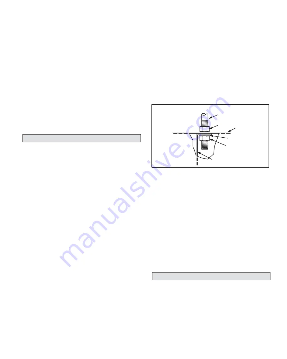
Suspended Installation
To suspend furnace, remove knockouts in top of panel at
warm air discharge and at blower panel (Refer to unit di-
mensions). Use 3/8" rods cut to desired length. Use one flat
washer and two nuts for each rod. One nut and the washer
on the inside of unit and the other nut on the outside of unit
(the locking nut). Level the unit by adjusting the nuts on the
inside of unit. See figure 3 to suspend unit.
rod
nut
top of
furnace
washer
nut
blower compartment
division panel
Hanger Rod Installation
Figure 3
B−Downflow Application
When installing the OHR23 in a downflow position and on
combustible flooring, a combustible floor base must be
used. See Unit Dimension illustration.
1− Rotate the furnace so that return is on top and supply is
on bottom. Refer to table 3 for clearances to combus-
tible flooring.
2− Remove the nuts in the bracket that hold the burner to
the furnace front. Rotate the burner and burner mount-
ing plate 90
and reinstall the nuts.
3− It is also recommended that the upper rear screw hold-
ing the blower housing to the blower deck be removed
before installation in a closet. Removing this screw al-
lows for easy service and removal of the blower as-
sembly in a closet installation.
Supply & Return Air Plenums
NOTE − The following are suggested procedures that
should be followed when installing the supply and return air
plenums.
1− Use sealing strips of fiberglass.
2− In all cases, the plenum should be secured to furnace
or evaporator cabinet with sheet metal screws.


