Page 126 - IOM / ROOF-TOP FLEXY™ Series
Rooftops are generally placed on the roof but can also be installed in technical rooms. These units are very robust but a
minimum regular maintenance is required. Some moving parts in the units can suffer from wear and tear and must be
checked regularly (belts). Other parts can get clogged by dirt carried in the air (filters) and must be cleaned or replaced.
These units are designed to produce cooled or heated air through the use of a refrigeration vapour compression system, it is
therefore imperative to monitor the refrigeration circuit operating pressures and check the pipe-work for leaks.
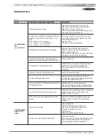
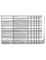
The table below, details a possible maintenance plan, including the operations to be carried out and the periodicity at which
they must be accomplished. It is recommended to follow such a plan to keep a rooftop unit in good working order. Regular
maintenance of your rooftop will extend its operating life and reduce operating faults
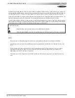
Symbols and Legend :
0
Operation which can be carried out by on-site maintenance technicians.
∆∆∆∆∆
Operation which
must
be carried out by qualified personnel, trained to operate on this type of equipment.
NOTE :
- Times are given for information purpose only and may vary depending on the unit size and type of installation.
- Coil cleaning must be carried out by qualified personnel using appropriate methods that won't damage the fins or the
tubes.
- It is recommended to keep a minimum stock of common replacement parts in order to be able to carry out regular
maintenance operations (i.e. filters). You can contact your local Lennox representative which can assist you in
establishing a parts list for each type of equipment.
- The access ports to the refrigeration circuits MUST be leak checked every time gauges are connected to the service
ports.
MAINTENANCE PLAN
Summary of Contents for ROOFTOP FLEXY FCA 100
Page 1: ...INSTALLATION OPERATING MAINTENANCE MANUAL ROOFTOP FLEXY English August 2003 ...
Page 2: ......
Page 33: ...IOM ROOF TOP FLEXY Series Page 31 AIR FLOW BALANCING AT 12 12 FAN ...
Page 34: ...Page 32 IOM ROOF TOP FLEXY Series AIR FLOW BALANCING AT 15 15 FAN ...
Page 35: ...IOM ROOF TOP FLEXY Series Page 33 AIR FLOW BALANCING AT 18 13 ...
Page 36: ...Page 34 IOM ROOF TOP FLEXY Series AIR FLOW BALANCING AT 18 18 FAN ...
Page 37: ...IOM ROOF TOP FLEXY Series Page 35 AIR FLOW BALANCING RDN 450 FAN ...
Page 38: ...Page 36 IOM ROOF TOP FLEXY Series AIR FLOW BALANCING ADN 355 FAN ...
Page 39: ...IOM ROOF TOP FLEXY Series Page 37 AIR FLOW BALANCING ADN 400 FAN ...
Page 40: ...Page 38 IOM ROOF TOP FLEXY Series AIR FLOW BALANCING ADN 450 FAN ...
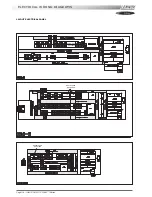
Page 104: ...Page 102 IOM ROOF TOP FLEXY Series ELECTRICAL WIRING DIAGRAMS MAIN CURRENT DIAGRAM ...
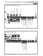
Page 106: ...Page 104 IOM ROOF TOP FLEXY Series ELECTRICAL WIRING DIAGRAMS CLIMATIC CONTROLLER ...
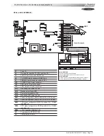
Page 108: ...Page 106 IOM ROOF TOP FLEXY Series ELECTRICAL WIRING DIAGRAMS CLIMATIC INPUT FG FD ...
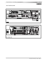
Page 112: ...Page 110 IOM ROOF TOP FLEXY Series ELECTRICAL WIRING DIAGRAMS GAS BURNER 180 Kw ...
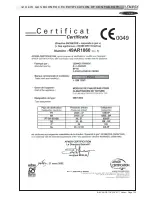
Page 132: ...Page 130 IOM ROOF TOP FLEXY Series ISO 9001 CERTIFICATION ...
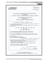
Page 133: ...IOM ROOF TOP FLEXY Series Page 131 PED CERTIFICATION OF CONFORMITY ...
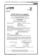
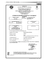
Page 134: ...Page 132 IOM ROOF TOP FLEXY Series GLASS WOOL FIRE CLASS ...
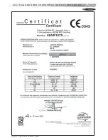
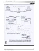
Page 135: ...IOM ROOF TOP FLEXY Series Page 133 33 kW GAS BURNER CE CERTIFICATION OF CONFORMITY ...
Page 136: ...Page 134 IOM ROOF TOP FLEXY Series 60 kW GAS BURNER CE CERTIFICATION OF CONFORMITY ...
Page 137: ...IOM ROOF TOP FLEXY Series Page 135 120 kW GAS BURNER CE CERTIFICATION OF CONFORMITY ...
Page 138: ...Page 136 IOM ROOF TOP FLEXY Series 180 kW GAS BURNER CE CERTIFICATION OF CONFORMITY ...
Page 139: ...IOM ROOF TOP FLEXY Series Page 137 INSULATION FIRE CLASS ...
Page 140: ...Page 138 IOM ROOF TOP FLEXY Series INSULATION FIRE CLASS ...
Page 141: ......

