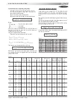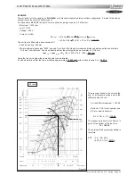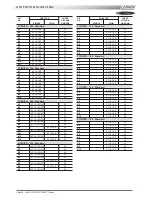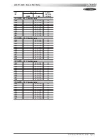
Page 22 - IOM / ROOF-TOP FLEXY™ Series
VENTILaTION : PULLEYS
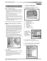
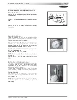
MOUNTING AND ADJUSTING PULLEYS
Fan pulley removal
Remove the 2 screws and put one of them in the extraction
threaded screw.
Screw in fully. The hub and the pulley will separate from each
other.
Remove the hub and the pulley by hand without damaging
the machine.
Fan pulley installation
Clean and de-grease the shaft, hub and conical bore of the
pulley. Lubricate the screws and install the hub and pulley.
Position the screws without turning them.
Place the assembly on the shaft and screw in the screws
alternatively and evenly. Using a mallet or a hammer with a
wooden wedge, tap on the face of the hub to keep the
assembly in place. Torque the screws to 30 Nm.
Take the pulley in both hands and shake it vigorously to make
sure everything is in place.
Fill the holes with grease for protection.
NOTE
: During installation, the key should never protrude out
of its groove.
After 50 operating hours, check that the screws are still in
place.
Motor pulley installation and removal
The pulley is held in position by the key and a screw located
in the groove. After unlocking, removing this screw by pulling
against the shaft spindle (if necessary, use a mallet and tap
uniformly on the hub to remove it).
To assemble, proceed in the reverse order after having
cleaned and de-greased the motor shaft and the pulley bore.
Pulleys alignment
After adjusting one or both of the pulleys, check the
transmission alignment using a ruler placed on the inner face
of the two pulleys.
NOTE
: The warranty may be affected if any major modification
is made to the transmission without obtaining our agreement
beforehand.
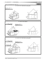
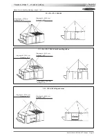
Figure 19
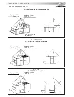
Figure 20
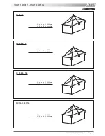
Figure 21
Summary of Contents for ROOFTOP FLEXY FCA 100
Page 1: ...INSTALLATION OPERATING MAINTENANCE MANUAL ROOFTOP FLEXY English August 2003 ...
Page 2: ......
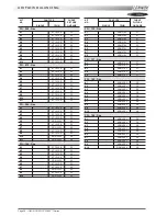
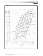
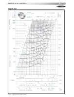
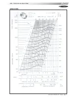
Page 33: ...IOM ROOF TOP FLEXY Series Page 31 AIR FLOW BALANCING AT 12 12 FAN ...
Page 34: ...Page 32 IOM ROOF TOP FLEXY Series AIR FLOW BALANCING AT 15 15 FAN ...
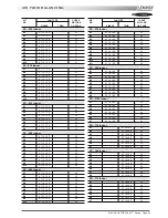
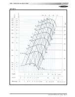
Page 35: ...IOM ROOF TOP FLEXY Series Page 33 AIR FLOW BALANCING AT 18 13 ...
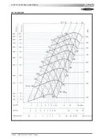
Page 36: ...Page 34 IOM ROOF TOP FLEXY Series AIR FLOW BALANCING AT 18 18 FAN ...
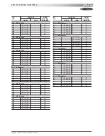
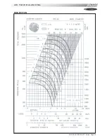
Page 37: ...IOM ROOF TOP FLEXY Series Page 35 AIR FLOW BALANCING RDN 450 FAN ...
Page 38: ...Page 36 IOM ROOF TOP FLEXY Series AIR FLOW BALANCING ADN 355 FAN ...
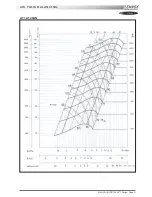
Page 39: ...IOM ROOF TOP FLEXY Series Page 37 AIR FLOW BALANCING ADN 400 FAN ...
Page 40: ...Page 38 IOM ROOF TOP FLEXY Series AIR FLOW BALANCING ADN 450 FAN ...
Page 104: ...Page 102 IOM ROOF TOP FLEXY Series ELECTRICAL WIRING DIAGRAMS MAIN CURRENT DIAGRAM ...
Page 106: ...Page 104 IOM ROOF TOP FLEXY Series ELECTRICAL WIRING DIAGRAMS CLIMATIC CONTROLLER ...
Page 108: ...Page 106 IOM ROOF TOP FLEXY Series ELECTRICAL WIRING DIAGRAMS CLIMATIC INPUT FG FD ...
Page 112: ...Page 110 IOM ROOF TOP FLEXY Series ELECTRICAL WIRING DIAGRAMS GAS BURNER 180 Kw ...
Page 132: ...Page 130 IOM ROOF TOP FLEXY Series ISO 9001 CERTIFICATION ...
Page 133: ...IOM ROOF TOP FLEXY Series Page 131 PED CERTIFICATION OF CONFORMITY ...
Page 134: ...Page 132 IOM ROOF TOP FLEXY Series GLASS WOOL FIRE CLASS ...
Page 135: ...IOM ROOF TOP FLEXY Series Page 133 33 kW GAS BURNER CE CERTIFICATION OF CONFORMITY ...
Page 136: ...Page 134 IOM ROOF TOP FLEXY Series 60 kW GAS BURNER CE CERTIFICATION OF CONFORMITY ...
Page 137: ...IOM ROOF TOP FLEXY Series Page 135 120 kW GAS BURNER CE CERTIFICATION OF CONFORMITY ...
Page 138: ...Page 136 IOM ROOF TOP FLEXY Series 180 kW GAS BURNER CE CERTIFICATION OF CONFORMITY ...
Page 139: ...IOM ROOF TOP FLEXY Series Page 137 INSULATION FIRE CLASS ...
Page 140: ...Page 138 IOM ROOF TOP FLEXY Series INSULATION FIRE CLASS ...
Page 141: ......

