Page 40 - IOM / ROOF-TOP FLEXY™ Series
VENTILaTION : FANSTART OPERATION
Current protection of the Thyristor
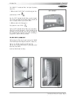
The FANSTART will display a fault (red LED) if the current
exceeds the thyristor current limits
125A during 0.4 s
87.4A during 2 s
75A during 6 s.
62.5A during 20 s.
Start up sequence too long
A fault (red LED) will appear if after 1min20s the FANSTART
Control is not bypassed and the motor running from the mains.
Phase rotation check
If the phase rotation is incorrect the FANSTART Control will
display a fault ( Red LED). Two of the phases must then be
inverted and the start up cycle resumed.
AIR SOCK CONTROL
The use of air socks for space conditioning allows high air
volumes to be distributed at low velocity and is becoming a
common feature in many applications. To accommodate this
trend, Air-sock control is offered which allows the air socks to
be progressively filled with air on start up. FLEXY™ has been
enhanced with an electronic device to soft start the fan. It
takes up to 1 minute to go from 0% of air to full air flow.
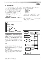
This time can be divided in several stages :
- The aim of this first voltage input is to overcome the
resistance of the transmission (Pulleys and belts) : 0.5s
and up to 1000 rpm
- The second stage is to inflate the air sock : 5 to 30 s.
and 600 to 900 rpm
Finally the air sock is gradually pressurised during the last 5
to 30 second. The motor reaches nominal speed and the
controller is bypassed.
The motor speed control is achieve through a variation of the
supply voltage of each phase at constant frequency.
The thermal overload limit on the motor imposes a current
limitation during the acceleration stage. Hence if the selected
slope is to steep, a predefined current limit can be reached
(potentiometer adjustment) and the controller will automatically
reduce the voltage set-point accordingly. Then once the current
is back under the high current limit it carries on with the start
up cycle.
Safety
Excessive "slow down" limit
The FANSTART will display a fault (red LED) and stop the
motor, if the motor slows down excessively (voltage could
reach 0V) because of the current limitation during the
acceleration stage.
Missing phase safety
The FANSTART will display a fault (red LED) if the current in
the third phase is too low or reaches 0 Amps (Three phase
supply or motor problem)
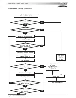
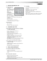
FAN START
OFF
MOTOR OFF
Green LED = 0
Red LED = 0
MOTOR OFF
Green LED = 1
Red LED = 1
Power + Control ON
Green LED = 1
Red LED = 0
Control ON
Power OFF
PHASE
ROTATION
CHECK
T°C Fault
Thyristor
OK
INFLATION
Green LED = 1
Red LED = 0
ACCELERATION
Green LED = 1
Red LED = 0
(If current control ON)
CONTROL OFF
motor connected
to mains
NOT OK
I > I max
Speed = 0
T > 1 min20s
I < Imin
I > I max
Speed = 0
T > 1 min20s
I < Imin
Current
1
st
voltage Input to Overcome
transmission performance
Over-current limit
A
ir sock
Inflation
5 to 30s
Acceleration 15 to 30s
FANSTART off
Figure 35
Figure 37
Summary of Contents for ROOFTOP FLEXY FCA 100
Page 1: ...INSTALLATION OPERATING MAINTENANCE MANUAL ROOFTOP FLEXY English August 2003 ...
Page 2: ......
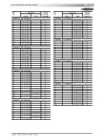
Page 33: ...IOM ROOF TOP FLEXY Series Page 31 AIR FLOW BALANCING AT 12 12 FAN ...
Page 34: ...Page 32 IOM ROOF TOP FLEXY Series AIR FLOW BALANCING AT 15 15 FAN ...
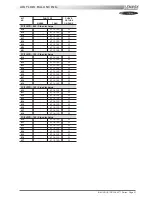
Page 35: ...IOM ROOF TOP FLEXY Series Page 33 AIR FLOW BALANCING AT 18 13 ...
Page 36: ...Page 34 IOM ROOF TOP FLEXY Series AIR FLOW BALANCING AT 18 18 FAN ...
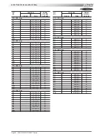
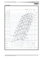
Page 37: ...IOM ROOF TOP FLEXY Series Page 35 AIR FLOW BALANCING RDN 450 FAN ...
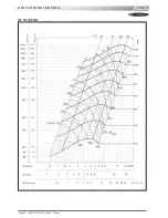
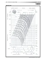
Page 38: ...Page 36 IOM ROOF TOP FLEXY Series AIR FLOW BALANCING ADN 355 FAN ...
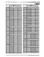
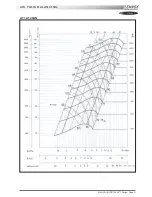
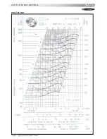
Page 39: ...IOM ROOF TOP FLEXY Series Page 37 AIR FLOW BALANCING ADN 400 FAN ...
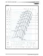
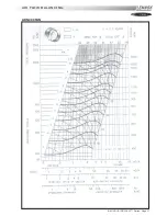
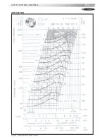
Page 40: ...Page 38 IOM ROOF TOP FLEXY Series AIR FLOW BALANCING ADN 450 FAN ...
Page 104: ...Page 102 IOM ROOF TOP FLEXY Series ELECTRICAL WIRING DIAGRAMS MAIN CURRENT DIAGRAM ...
Page 106: ...Page 104 IOM ROOF TOP FLEXY Series ELECTRICAL WIRING DIAGRAMS CLIMATIC CONTROLLER ...
Page 108: ...Page 106 IOM ROOF TOP FLEXY Series ELECTRICAL WIRING DIAGRAMS CLIMATIC INPUT FG FD ...
Page 112: ...Page 110 IOM ROOF TOP FLEXY Series ELECTRICAL WIRING DIAGRAMS GAS BURNER 180 Kw ...
Page 132: ...Page 130 IOM ROOF TOP FLEXY Series ISO 9001 CERTIFICATION ...
Page 133: ...IOM ROOF TOP FLEXY Series Page 131 PED CERTIFICATION OF CONFORMITY ...
Page 134: ...Page 132 IOM ROOF TOP FLEXY Series GLASS WOOL FIRE CLASS ...
Page 135: ...IOM ROOF TOP FLEXY Series Page 133 33 kW GAS BURNER CE CERTIFICATION OF CONFORMITY ...
Page 136: ...Page 134 IOM ROOF TOP FLEXY Series 60 kW GAS BURNER CE CERTIFICATION OF CONFORMITY ...
Page 137: ...IOM ROOF TOP FLEXY Series Page 135 120 kW GAS BURNER CE CERTIFICATION OF CONFORMITY ...
Page 138: ...Page 136 IOM ROOF TOP FLEXY Series 180 kW GAS BURNER CE CERTIFICATION OF CONFORMITY ...
Page 139: ...IOM ROOF TOP FLEXY Series Page 137 INSULATION FIRE CLASS ...
Page 140: ...Page 138 IOM ROOF TOP FLEXY Series INSULATION FIRE CLASS ...
Page 141: ......

