IOM / ROOF-TOP FLEXY™ Series - Page 65
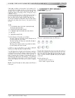
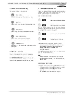
USING THE KP02 MAINTENANCE CONTROL DISPLAY
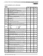
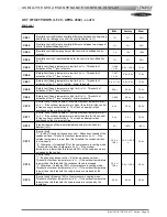
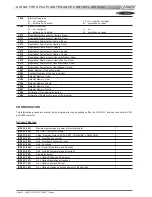
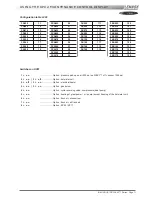
LIST OF SETPOINTS (LF 20 - APRIL 2002) - cont'd
2nd Level
Mini. Factory Maxi.
C 061
[Humidity control] Relative humidity difference between the beginning
and the end of a stage of control in dehumidification (in %)
1 %
3 %
50 %
C 062
[Humidity control] Relative humidity difference between two stages of
control in dehumidification (in %)
1 %
3 %
50 %
C 063
[Humidity control] Sampling time of the control in humidification (in
seconds)
1 s
10 s
120 s
C 064
[Humidity control] Proportional band for the control in humidification
(in %)
1 %
5 %
50 %
C 065
[Safety limit] Supply temperature low limit (in °c) - Threshold of
activation of the 1
st
level of safety.
C 066
+ 2.0 c
8.0c / 10.0 c
19.0 c
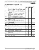
C 066
[Safety limit] Supply temperature low limit (in °c) - Threshold of
activation of the 2
nd
level of safety.
C 067
+ 2.0 c
6.0c / 8.0 c
17.0 c
C 067
[Safety limit] Supply temperature low limit (in °c) - Threshold of
activation of the 3
rd
level of safety. - Alarm threshold
5.0 c / 1.0 c
2.0c / 6.0 c
15.0 c
C 068
[Safety limit] Supply temperature high limit (in °c) - Threshold of
activation of the 1
st
level of safety
20.0 c
40.0 c
70.0 c
C 069
[Safety limit] Supply temperature high limit (in °c) - Threshold of
activation of the 2
nd
level of safety. - Alarm threshold
C 068
60.0 c
70.0 c
C 070
[Control limit] Fresh air damper - Maximum outdoor temperature limit
(in °c). - If the outdoor temperature is higher than this limit the control
in free-cooling is not authorized. - The fresh air damper is then
positioned on the minimum setting.
0.0 c
26.0 c
60.0 c
C 071
[Control limit] Fresh air damper – Minimum outdoor temperature limit
(in °c). - If the outdoor temperature is lower than this limit the control
in free-cooling is not authorized. - The fresh air damper is then
positioned on the minimum setting.
0.0 c
5.0 c
30.0 c
C 072
[Fresh air damper] Maximum allowable opening for the fresh air
damper (in %)
0 %
100 %
100 %
C 073
[Control limit]
* 1° (FLEXY) If option all seasons control - Reduction of speed of the
condenser fans - Threshold of outdoor temperature (in °c). - If the
outside temperature is lower than this threshold the condenser fans
run low speed
* 2° Otherwise – Unloading 50% of the compressors in cooling mode
- Threshold of outdoor temperature (in °c). - If the outdoor
temperature is lower than this threshold 50% of the compressors are
unloaded by the control.
-10.0 c /
10.0 c
12.0 c / 20.0
c
30.0 c
C 074
[Control limit]
* 1° If option all seasons control – Shut down condenser fans -
Threshold of outdoor temperature (in °c). - If the outdoor temperature
is lower than this threshold the condenser fans are stopped
* 2° Otherwise - Unloading 100% of compressors in cooling mode -
Threshold of outdoor temperature (in °c). - If the outdoor temperature
is lower than this threshold the compressors are stopped by the
control
-10.0 c /
10.0 c
5.0 c / 12.0 c
30.0 c
C 075
[Control limit] Unloading 100% of compressors in heating mode -
Threshold of outdoor temperature (in °c). - If the outdoor temperature
is lower than this threshold the compressors are not used by the
regulation
-50.0 c
-20.0 c
20.0 c
Summary of Contents for ROOFTOP FLEXY FCA 100
Page 1: ...INSTALLATION OPERATING MAINTENANCE MANUAL ROOFTOP FLEXY English August 2003 ...
Page 2: ......
Page 33: ...IOM ROOF TOP FLEXY Series Page 31 AIR FLOW BALANCING AT 12 12 FAN ...
Page 34: ...Page 32 IOM ROOF TOP FLEXY Series AIR FLOW BALANCING AT 15 15 FAN ...
Page 35: ...IOM ROOF TOP FLEXY Series Page 33 AIR FLOW BALANCING AT 18 13 ...
Page 36: ...Page 34 IOM ROOF TOP FLEXY Series AIR FLOW BALANCING AT 18 18 FAN ...
Page 37: ...IOM ROOF TOP FLEXY Series Page 35 AIR FLOW BALANCING RDN 450 FAN ...
Page 38: ...Page 36 IOM ROOF TOP FLEXY Series AIR FLOW BALANCING ADN 355 FAN ...
Page 39: ...IOM ROOF TOP FLEXY Series Page 37 AIR FLOW BALANCING ADN 400 FAN ...
Page 40: ...Page 38 IOM ROOF TOP FLEXY Series AIR FLOW BALANCING ADN 450 FAN ...
Page 104: ...Page 102 IOM ROOF TOP FLEXY Series ELECTRICAL WIRING DIAGRAMS MAIN CURRENT DIAGRAM ...
Page 106: ...Page 104 IOM ROOF TOP FLEXY Series ELECTRICAL WIRING DIAGRAMS CLIMATIC CONTROLLER ...
Page 108: ...Page 106 IOM ROOF TOP FLEXY Series ELECTRICAL WIRING DIAGRAMS CLIMATIC INPUT FG FD ...
Page 112: ...Page 110 IOM ROOF TOP FLEXY Series ELECTRICAL WIRING DIAGRAMS GAS BURNER 180 Kw ...
Page 132: ...Page 130 IOM ROOF TOP FLEXY Series ISO 9001 CERTIFICATION ...
Page 133: ...IOM ROOF TOP FLEXY Series Page 131 PED CERTIFICATION OF CONFORMITY ...
Page 134: ...Page 132 IOM ROOF TOP FLEXY Series GLASS WOOL FIRE CLASS ...
Page 135: ...IOM ROOF TOP FLEXY Series Page 133 33 kW GAS BURNER CE CERTIFICATION OF CONFORMITY ...
Page 136: ...Page 134 IOM ROOF TOP FLEXY Series 60 kW GAS BURNER CE CERTIFICATION OF CONFORMITY ...
Page 137: ...IOM ROOF TOP FLEXY Series Page 135 120 kW GAS BURNER CE CERTIFICATION OF CONFORMITY ...
Page 138: ...Page 136 IOM ROOF TOP FLEXY Series 180 kW GAS BURNER CE CERTIFICATION OF CONFORMITY ...
Page 139: ...IOM ROOF TOP FLEXY Series Page 137 INSULATION FIRE CLASS ...
Page 140: ...Page 138 IOM ROOF TOP FLEXY Series INSULATION FIRE CLASS ...
Page 141: ......

