Page 66 - IOM / ROOF-TOP FLEXY™ Series
USING THE KP02 MAINTENANCE CONTROL DISPLAY
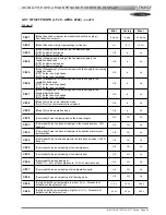
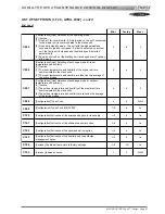
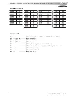
LIST OF SETPOINTS (LF 20 - APRIL 2002) - cont'd
2nd Level
Mini. Factory Maxi.
C 076
[Defrost function] Authorization of defrost - Threshold of outdoor
temperature (in °c)
8.0 c
10.0 c /
20.0 c
20.0 c
C 077
[Defrost function] Authorization of defrost - Threshold of temperature
of refrigerant fluid (in °c)
-10.0 c
2.0 c /
-2.0 c
6.0 c
C 078
[Defrost function] Coil icing time (in minute) - The defrost cycle starts
if the operating time of a compressor in heat pump mode reached this
value
30 m
30 m / 45 m
90 m
C 079
[Defrost function] Defrost cycle end - Value indicating the number of
start-up of the condenser fan by the pressure switch to signify the end
of the defrost cycle
1 1
/
3 5
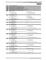
C 080
[Safety limit] Water heat exchanger output temperature low limit (in
°c) - Threshold of activation of the safety
4.0 c
5.0 c
20.0 c
C 081
[Safety limit] Water heat exchanger output temperature high limit (in
°c) - Threshold of activation of the safety
20.0 c
45.0 c
46.0 c
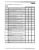
C 082
[Control limit] Unloading 100% of electrical heat - Threshold of
outdoor temperature (in °c). If the outdoor temperature is higher than
this threshold electrical heat are switched off by the control
-20.0 c
10.0 c
30.0 c
C 083
[Electric heat] Maximum usable power for electric heat (in %)
0 %
100 %
100 %
C 084
[Electric heat] (FLEXY FX) All season control - Threshold of mixed air
temperature (in °c) - If the mixed air temperature is lower than this
threshold electric heat is activated
0.0 c
5.0 c
10.0 c
C 085
[Safety limit] Air flow detection - Threshold of pressure difference for
the loss of pressure detection (in pa) - If the pressure difference
across the filters is lower than this threshold the safety is activated.
0 pa
20 pa
1000 pa
C 086
[Safety limit] Clogged filter detection– Threshold of pressure
difference for the detection of clogging (in pa) - If the pressure
difference across the filters is higher than this threshold the safety is
activated
0 pa
250 pa
1000 pa
C 087
[Safety limit] Missing filter detection - Threshold of pressure
difference for the detection of missing filters (in pa) - If the pressure
difference across the filter is lower than this threshold the safety is
activated
0 pa
50 pa
1000 pa
C 088
[kp12-2] Time delay for the closing of contact n°3 (in seconds)
4 s
60 s
65535 s
C 089
[kp12-2] Time delay for the opening of the contact n°2 (in seconds)
2 s
300 s
65535 s
C 090
[kp17] Choice of operating mode –
[Off] Left button = Forcing day mode / Medium button = Cancel
forcing / Right button = Forcing night mode –
[On] Left button = Start the unit / Right button = Stop the unit
Off # On
C 091
[Configuration] Identification number for the j-bus connections
1 #
255
C 092
[BMS] Activation of the control by a computer or an automat - Mode
BMS is activated if this value is different from zero, this value is
decreased every second
0 0
65535
C 093
[Configuration] [Link] Identification number for the connections link
between boards
0 # 7
C 094
[Configuration] [Link] Number of boards linked on the bus
0 # 8
Summary of Contents for ROOFTOP FLEXY FCA 100
Page 1: ...INSTALLATION OPERATING MAINTENANCE MANUAL ROOFTOP FLEXY English August 2003 ...
Page 2: ......
Page 33: ...IOM ROOF TOP FLEXY Series Page 31 AIR FLOW BALANCING AT 12 12 FAN ...
Page 34: ...Page 32 IOM ROOF TOP FLEXY Series AIR FLOW BALANCING AT 15 15 FAN ...
Page 35: ...IOM ROOF TOP FLEXY Series Page 33 AIR FLOW BALANCING AT 18 13 ...
Page 36: ...Page 34 IOM ROOF TOP FLEXY Series AIR FLOW BALANCING AT 18 18 FAN ...
Page 37: ...IOM ROOF TOP FLEXY Series Page 35 AIR FLOW BALANCING RDN 450 FAN ...
Page 38: ...Page 36 IOM ROOF TOP FLEXY Series AIR FLOW BALANCING ADN 355 FAN ...
Page 39: ...IOM ROOF TOP FLEXY Series Page 37 AIR FLOW BALANCING ADN 400 FAN ...
Page 40: ...Page 38 IOM ROOF TOP FLEXY Series AIR FLOW BALANCING ADN 450 FAN ...
Page 104: ...Page 102 IOM ROOF TOP FLEXY Series ELECTRICAL WIRING DIAGRAMS MAIN CURRENT DIAGRAM ...
Page 106: ...Page 104 IOM ROOF TOP FLEXY Series ELECTRICAL WIRING DIAGRAMS CLIMATIC CONTROLLER ...
Page 108: ...Page 106 IOM ROOF TOP FLEXY Series ELECTRICAL WIRING DIAGRAMS CLIMATIC INPUT FG FD ...
Page 112: ...Page 110 IOM ROOF TOP FLEXY Series ELECTRICAL WIRING DIAGRAMS GAS BURNER 180 Kw ...
Page 132: ...Page 130 IOM ROOF TOP FLEXY Series ISO 9001 CERTIFICATION ...
Page 133: ...IOM ROOF TOP FLEXY Series Page 131 PED CERTIFICATION OF CONFORMITY ...
Page 134: ...Page 132 IOM ROOF TOP FLEXY Series GLASS WOOL FIRE CLASS ...
Page 135: ...IOM ROOF TOP FLEXY Series Page 133 33 kW GAS BURNER CE CERTIFICATION OF CONFORMITY ...
Page 136: ...Page 134 IOM ROOF TOP FLEXY Series 60 kW GAS BURNER CE CERTIFICATION OF CONFORMITY ...
Page 137: ...IOM ROOF TOP FLEXY Series Page 135 120 kW GAS BURNER CE CERTIFICATION OF CONFORMITY ...
Page 138: ...Page 136 IOM ROOF TOP FLEXY Series 180 kW GAS BURNER CE CERTIFICATION OF CONFORMITY ...
Page 139: ...IOM ROOF TOP FLEXY Series Page 137 INSULATION FIRE CLASS ...
Page 140: ...Page 138 IOM ROOF TOP FLEXY Series INSULATION FIRE CLASS ...
Page 141: ......

