background image

Page 50

Unit Start-Up

FOR YOUR SAFETY READ BEFORE OPERATING

 WARNING

Do not use this furnace if any part has been underwater. 

A  flood-damaged  furnace  is  extremely  dangerous. 

Attempts to use the furnace can result in fire or explosion. 

Immediately call a qualified service technician to inspect 

the furnace and to replace all gas controls, control 

system parts, and electrical parts that have been wet or 

to replace the furnace, if deemed necessary.

 WARNING

Danger of explosion. Can cause injury or 

product or property damage. Should the gas 

supply fail to shut off or if overheating occurs, 

shut off the gas valve to the furnace before 

shutting off the electrical supply.

 CAUTION

Before attempting to perform any service or maintenance, 

turn the electrical power to unit OFF at disconnect switch.

 WARNING

During blower operation, the ECM motor emits 

energy that may interfere with pacemaker operation. 

Interference is reduced by both the sheet metal cabinet 

and distance.

Priming Condensate Trap

The condensate trap should be primed with water prior 

to start-up to ensure proper condensate drainage. Either 

pour  10  fl.  oz.  (300  ml)  of  water  into  the  trap,  or  follow 

these steps to prime the trap:

1 -   Follow the lighting instructions to place the unit into 

operation.

2 -  Set the thermostat to initiate a heating demand.
3 - 

 Allow the burners to fire for approximately 3 minutes.

4 -   Adjust the thermostat to deactivate the heating 

demand.

5 -   Wait for the combustion air inducer to stop. Set the 

thermostat to initiate a heating demand and again 

allow the burners to fire for approximately 3 minutes.

6 -   Adjust the thermostat to deactivate the heating 

demand and again wait for the combustion air 

inducer to stop. At this point, the trap should be 

primed  with  sufficient  water  to  ensure  proper 

condensate drain operation.

BEFORE BEFORE PLACING THE UNIT INTO OPERA-

TION, 

smell all around the furnace area for gas. Be sure 

to  smell  next  to  the  floor  because  some  gas  is  heavier 

than air and will settle on the floor. The gas valve on the 

SLP99DFV is equipped with a gas control switch. Use only 

your hand to move the control switch. Never use tools. If 

the switch will not move by hand, do not try to repair it. 

Force or attempted repair may result in a fire or explosion.

Placing the furnace into operation:

SLP99DFV units are equipped with an automatic ignition 

system. Do not attempt to manually light burners on this 

furnace. Each time the thermostat calls for heat, the burn-

ers will automatically light. The ignitor does not get hot 

when there is no call for heat on units with this ignition 

system.

 WARNING

If you do not follow these instructions exactly, a fire or 

explosion may result causing property damage, personal 

injury or death.

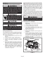
Gas Valve Operation (FIGURE 51)

1 -   

STOP! 

Read the safety information at the beginning 

of this section.

2 -   Set the thermostat to the lowest setting.
3 - 

Turn off all electrical power to the unit.

4 -   This furnace is equipped with an ignition device 

which automatically lights the burners. Do not try to 

light the burners by hand.

5 -  Remove the access panel.
6 -   Move the gas valve switch to the OFF position. See 

FIGURE 51.

7 - 

 Wait five minutes to clear out any gas. If you then 

smell gas, STOP! Immediately call the gas supplier 

from a neighbor’s phone. Follow the gas supplier’s 

instructions. If you do not smell gas go to next step.

8 -   Move gas valve switch to the ON position. See 

FIGURE 51. Do not force.

GAS VALVE

NEGATIVE AIR

PRESSURE PORT

POSITIVE AIR

PRESSURE PORT

MANIFOLD

PRESSURE TAP

INLET

OUTLET

SUPPLY

PRESSURE

TAP

GAS VALVE SHOWN IN THE ON POSITION

FIGURE 51


Summary of Contents for SIGNATURE SLP99DF070V36

Page 1: ...cations the Lennox ComfortSense 7500 thermostat may be used as well as other non communicating thermostats In all cases setup is critical to ensure proper system operation Field wiring for both commun...

Page 2: ...ly Air Supply Air 9 16 14 9 16 14 9 16 14 9 16 14 19 7 16 494 3 4 19 CONDENSATE TRAP CONNECTION 5 127 6 7 16 163 Either Side 9 229 Either Side 2 1 4 57 Either Side 1 1 2 38 Front Panel Flue Condensate...

Page 3: ...PANEL COMBUSTION AIR INDUCER BLOWER ACCESS PANEL BLOWER ASSEMBLY Variable Speed Blower Motor Is Hidden BAG ASSEMBLY CONTROL BOX includes variable capacity integrated control transformer circuit breake...

Page 4: ...ipment and wear gloves and protective clothing Use only the type of gas approved for use with this fur nace Refer to unit nameplate Building Codes In the USA installation of gas furnaces must conform...

Page 5: ...signed for installation in mobile homes recreational vehicles or outdoors Never use an open flame to test for gas leaks Check all connections using a commercially available soap solution made specific...

Page 6: ...in an unconditioned space consider provisions required to prevent freezing of condensate drain system Installation Setting Equipment WARNING Do not install the furnace on its front back or in the hor...

Page 7: ...system The base must provide a stable support and an airtight seal to the furnace Allow absolutely no sagging cracks gaps etc For no reason should return and supply air duct systems ever be connected...

Page 8: ...1 2 11M60 22 559 18 3 4 476 C Cabinet 21 11M61 22 559 22 3 4 578 FURNACE SUPPLY AIR PLENUM COMBUSTIBLE FLOORING BASE PROPERLY SIZED FLOOR OPENING FIGURE 9 2 After opening is cut set combustible floori...

Page 9: ...Specifications bulletin Additional information is provided in Service and Application Note ACC002 August 2000 TABLE 3 Furnace Cabinet Width Fillter Size B Cabinet 17 1 2 16 X 25 X 1 1 C Cabinet 21 1 2...

Page 10: ...ion Downflow SLP99DF Model a b 1 Mounting Surface 070XV36B 6 Center Plenum Duct 090XV36C 090XV48C 090XV60C 110XV60C Discharge Air Sensor Location and Wiring Downflow AIR FLOW DISCHARGE AIR SENSOR TERM...

Page 11: ...and intake connections are made of PVC Use PVC primer and solvent cement when using PVC vent pipe When using ABS vent pipe use transitional solvent cement to make connections to the PVC fittings in t...

Page 12: ...rnal to the structure Any vent pipe or elbows external to the structure must be included in total vent length calculations See vent length tables Kits must be properly installed according to kit instr...

Page 13: ...side of the top cap to the furnace Use 2 self drilling sheet metal screws provided to finish securing the left edge of the patch plate on the left side 9 Use a utility knife to cut out the cabinet ins...

Page 14: ...eral coat of PVC primer for PVC or use a clean dry cloth for ABS to clean inside socket surface of fitting and male end of pipe to depth of fitting socket 6 Promptly apply solvent cement to end of pip...

Page 15: ...azard Cutting or altering exhaust or air intake pipes which are located in the blower compartment could result in Carbon Monoxide Poisoning or Death CAUTION Do not discharge exhaust into an existing s...

Page 16: ...ing of vent systems which include multiple pipe sizes NOTE If right side venting option is used you must in clude the elbow at the furnace in the elbow count If tran sitioning to 3 dia pipe this elbow...

Page 17: ...9 51 29 100 53 122 103 78 10 46 24 95 48 117 98 73 Standard Termination at Elevation 4501 7500 Number of 90 Elbows Used 1 1 2 Pipe 2 Pipe 2 1 2 Pipe 3 Pipe Model Model Model Model 070 090 110 070 090...

Page 18: ...2 85 44 101 94 69 Concentric Termination at Elevation 4501 7500 Number of 90 Elbows Used 1 1 2 Pipe 2 Pipe 2 1 2 Pipe 3 Pipe Model Model Model Model 070 090 110 070 090 110 070 090 110 070 090 110 1 N...

Page 19: ...upling The provided flue coupling must be attached to the exhaust coupling on the furnace top panel Use provided bands See steps below and FIGURE 22 1 Remove the caution tag from the flue coupling 2 F...

Page 20: ...must be the same diameter Pipe Length 4 Maximum Not Furnished 2 2 Plate Furnished Street Ell Not Furnished FIGURE 23 TRANSITION 2 3 TOP VIEW 2 When transitioning up in pipe size use the shortest leng...

Page 21: ...e under veranda porch deck or balcony 12 7 feet 2 1m 3 feet 9m within a height 15 feet 4 5m above the meter regulator assembly 3 feet 9m 6 inches 152mm for appliances 10 000 pliances 10 000 Btuh 3kw a...

Page 22: ...the average snow accu mulation At vent termination care must be taken to maintain protec tive coatings over building materials prolonged exposure to exhaust condensate can destroy protective coatings...

Page 23: ...o 99 Minimum Design Temperature table provided in the current edition of the ASHRAE Fundamentals Handbook 2 Poly Propylene vent pipe PP by Duravent and Centrotherm 3Vent lengths in table are equivalen...

Page 24: ...separation requirement of intake and exhaust pipe DOES NOT apply 3 On roof terminations the intake piping should terminate straight down using two 90 elbows See FIGURE 28 4 Exhaust piping must termina...

Page 25: ...RMINATION 71M80 69M29 or 60L46 US 44W92 or 44W93 Canada INTAKE AIR EXHAUST AIR INTAKE AIR INTAKE AIR EXHAUST AIR OUTSIDE WALL GRADE CLAMP Not Furnished FIELD PROVIDED REDUCER MAY BE REQUIRED TO ADAPT...

Page 26: ...7 mm Min 12 305 mm Min 16 405 mm Max 6 152 mm Max 6 152 mm Min 24 610 mm Max 9 227 mm Min 12 305 mm Min 20 508 mm Max 6 152 mm Max Intake Elbow WALL SUPPORT B A D E B D E A ALTERNATE TERMINATIONS TEE...

Page 27: ...Install the cap over the clean out opening at the base of the trap Secure with clamp See FIGURE 43 3 Install drain trap using appropriate PVC fittings glue all joints Glue the provided drain trap as s...

Page 28: ...or Coil Using a Separate Drain Drain Field Provided Vent 1 min 2 max above condensate drain Condensate Drain Connection Evaporator Drain Line vent required FIGURE 40 IMPORTANT When combining the furna...

Page 29: ...rain Connection In Unit Condensate Drain Connection In Unit Vent To Drain Condensate Drain Connection In Unit Optional Condensate Drain Connection OptionalDrainPipingFromTrap DrainTrapAssembly Furnish...

Page 30: ...tate test gauge connection See FIGURE 51 6 In some localities codes may require installation of a manual main shut off valve and union furnished by installer external to the unit Union must be of the...

Page 31: ...930 360 10 19 247 7 000 199 5 63 170 4 81 151 4 23 137 3 87 126 3 56 117 3 31 110 3 11 104 2 94 1 25 4 1 049 26 645 678 19 19 466 13 19 374 10 59 320 9 06 284 8 04 257 7 27 237 6 71 220 6 23 207 5 86...

Page 32: ...or other deficiencies which could cause an unsafe condition 3 Close all building doors and windows and all doors between the space in which the appliances remaining connected to the common venting sy...

Page 33: ...hermostat wiring in communicating applications TABLE 15 shows DIP switch and on board link settings for non communicating thermostat applica tions 1 The power supply wiring must meet Class I restricti...

Page 34: ...9DFV is designed to operate in a variable rate capacity mode using a two stage thermostat The SLP99DFV will automatically adjust firing rate based upon thermostat cycle times A communicating thermosta...

Page 35: ...icating Thermostat Single wire to terminal C Single wire to terminal C Unused wires Unused wires Communicating systems using the a communicating thermostat require four thermostat wires between the th...

Page 36: ...S BUILT INTO ALL COMMUNICATING OUTDOOR UNITS COMMUNICATING ENABLED FURNACE HEPA BYPASS FILTER X2680 HEPA INTERLOCK KIT PASS INDOOR BLOWER MOTOR COMMON WIRE THROUGH CURRENT LOOP SEE HEPA INTERLOCK KIT...

Page 37: ...set second stage heat ON delay OFF 7 minutes ON 12 minutes ON Intact Intact Intact S1 T STAT CONTROL TERM STRIP OUTDOOR UNIT 1 Heat 2 Cool NOTE Use DIP switch 3 to set second stage heat ON delay OFF 7...

Page 38: ...itch 1 W915 Y1 to Y2 Two Stage Cooling W914 DS to R cation or Harmony III W951 O to R Heat Pumps 2 Heat 2 Cool OFF Cut Intact Intact S1 T STAT CONTROL TERM STRIP OUTDOOR UNIT 2 Heat 2 Cool with t stat...

Page 39: ...2 stage gas heat control DIP Switch 1 OFF Intact Intact Cut L7742U T STAT CONTROL TERM STRIP HEAT PUMP 67M41 Y H L Y2 D B L Y2 T T outdoor sensor Dual Fuel Two Stage Heat Pump ComfortSense 7000 L7742U...

Page 40: ...Page 40 FIGURE 49...

Page 41: ...IDIFICATION SIGNAL W2 HEAT DEMAND FROM 2ND STAGE T STAT W1 HEAT DEMAND FROM 1ST STAGE T STAT R CLASS 2 VOLTAGE TO THERMOSTAT G MANUAL FAN FROM T STAT C THERMOSTAT SIGNAL GROUND CONNECTED TO TRANSFORME...

Page 42: ...rate of the unit is varied to maximize comfort Conventional two stage mode is the factory default set ting See TABLE 16 Switch 3 Second Stage Heat On Delay If a single stage thermostat is used the in...

Page 43: ...ing Blower speed ramping may be used to enhance dehumidification performance The switches are factory set at option A which has the greatest effect on blower motor performance TABLE 21 provides the co...

Page 44: ...e in second stage cooling only Diagnostic LED FIGURE 50 The seven segment diagnostic LED displays operating status target airflow error codes and other information See Integrated Control Diagnostic Co...

Page 45: ...fault Heat CFM 629 669 749 829 910 990 1070 1150 Decrease 7 5 Heat CFM 559 599 681 763 845 927 1009 1091 Decrease 15 Heat CFM 488 530 614 697 781 865 948 1032 COOLING BLOWER PERFORMANCE 0 through 1 0...

Page 46: ...ult Heat CFM 553 618 748 878 1009 1139 1269 1399 Decrease 7 5 Heat CFM 510 570 690 811 931 1051 1171 1292 Decrease 15 Heat CFM 467 522 632 743 853 963 1074 1184 COOLING BLOWER PERFORMANCE 0 through 1...

Page 47: ...470 1655 1845 The effect of static pressure is included in air volumes shown The following control configurations are available See Installation Instructions for details and DIP switch settings Heat M...

Page 48: ...on a call for de humidification Dehumidification call 2 On On On Demand 0 VAC High 70 PRECISION MODE operates independent of a Y1 demand Normal Operation 1 On On On Acceptable 24 VAC High 100 Dehumidi...

Page 49: ...High 70 Thermostat will keep outdoor unit energized after cooling temperature setpoint has been reached in order to maintain room humidity setpoint ROOM THERMOSTAT CALLS FOR FIRST AND SECOND STAGE CO...

Page 50: ...to stop At this point the trap should be primed with sufficient water to ensure proper condensate drain operation BEFORE BEFORE PLACING THE UNIT INTO OPERA TION smell all around the furnace area for g...

Page 51: ...level Units installed at altitude of 7 501 to 10 000 feet 2287 to 3048m require a pressure switch change and conversion kit See TABLE 31 The combustion air pressure switch is factory set and re quires...

Page 52: ...tude Pressure Switch 0 10 000 ft 0 3048m 0 7500 ft 0 2286m 7501 ft 10 000 ft 287 3048m 070 65W77 Not Required 14T67 090 110 Operating Pressure Signal Delta P Measurement FIGURE 53 Operating pressure s...

Page 53: ...Installed Gas Valve MANIFOLD PRESSURE MEASUREMENT FIGURE 52 Negative Port Positive Port Gas Valve Measuring Device Field Installed Operating Signal Delta P Measurement Black Tubing Red and Black Tubi...

Page 54: ...r the correct voltage at the furnace furnace operating Correct voltage is 120VAC 10 3 Check amp draw on the blower motor with innerlower panel in place Motor Nameplate__________Actual__________ Electr...

Page 55: ...20 second warm up period has ended the gas valve is energized and ignition occurs At the same time the control module begins an indoor blower 45 second ON delay When the delay ends the indoor blower m...

Page 56: ...ance At the beginning of each heating season and to compl ith the Lennox Limited Warranty your system should be checked as follows 1 Check wiring for loose connections voltage at indoor unit and amper...

Page 57: ...er box cover 4 Disconnect the gas supply line from the gas valve Remove gas valve manifold assembly 5 Mark and disconnect sensor wire from the sensor Disconnect2 pin plug from the ignitor at the burne...

Page 58: ...horizontal bars will display Steps to follow if the damper control module is displaying the soft disable code Confirm proper wiring between all devices thermostat damper control module indoor and out...

Page 59: ...water column pressure of high pressure switch on heat call measure inches of water column of operating pressure inspect vent and combustion air inducer for correct operation and restriction E226 High...

Page 60: ...de is lower than cfm setting Restricted airflow Indoor blower is running at a reduced cubic feet per minute Cutback Mode The variable speed motor has pre set speed and torque limiters to protect the m...

Page 61: ...e solid P symbol is displayed on the 7 segment LED Release button This mode allows the user to select a unit size code number that matches the furnace model size and capacity Solid P starts blinking o...

Page 62: ...rial Wait For Ignition Stabilization Delay Post Purge 20Seconds Soft Lockout Error Code Flashes YES NO NO YES Call For Heat Ends NO YES YES NO C A L L F O R 1 S T S T A G E H E A T 3A 2 1 1 OR Call Fo...

Page 63: ...Closes Within 10 Seconds NO Error Code Flashes NO YES Wait 5 Minutes 3A 2 1 2 1 System will always light at 70 even if 2nd stage call for heat is in place If the high pressure switch does not close w...

Page 64: ...Closes Within 10 Seconds NO Error Code Flashes NO YES Wait 5 Minutes 3A 2 1 2 1 System will always light at 70 even if 2nd stage call for heat is in place If the high pressure switch does not close w...

Page 65: ...20 Seconds Soft Lockout Error Code Flashes YES NO NO YES Call For Heat Ends NO YES YES NO C A L L F O R H E A T 3B 1 4 Move to Mid Firing Rate and High Firing Rate after 2nd and 3rd Stage Delays base...

Page 66: ...gize and Low Cooling mode High Cooling mode High Cooling mode Per Ramping Profile NO NO YES NO 5 1 2 1 2 2 2 1 Indoor Blower On After 2 second delay Energize Indoor Blower Per Ramping Profile Energize...

Page 67: ...S NO YES Go to Call for Cooling 6 1 4 5 1 Call for Continuous Blower Indoor Blower On Maintain Indoor Blower at set speed Maintain Indoor Blower at set speed OR Maintain Indoor Blower at set speed Ind...

Page 68: ...ng at a minimum height of eight 8 feet above grade directly in line with the exhaust vent terminal for the horizontally vented gas fueled heating appliance or equipment The sign shall read in print si...

Page 69: ...rovinces of Canada Lennox approves the following termination for use in all provices of Canada C 12 D B A 2 51MM Vent Pipe 3 76MM Vent Pipe 12 305 mm Min 12 305 mm Min 6 152 mm Min 24 610 mm Max 6 152...

Page 70: ...pes Supported Condensate Trap Primed Line Sloped Heat Cable Installed and Operable if applicable 2 2 2 1 Horizontal Pipes Sloped if applicable UNIT SET UP typical 3 4 Flter RETURN AIR Furnace Model Nu...

Page 71: ...5 Supply External Static _______ Return External Static ______ Total External Static _______ CONDENSATE LINE 6 Leak Free VENT PIPE 7 Leak Free COOLING MODE INDOOR BLOWER AMPS______ 3 TEMPERATURE DROP...

Reviews: