background image

Page 10

505331M 06/09

2

3

4

5

6

outdoor

UNIT

LIQUID LINE

SUCTION LINE

SERVICE

VALVE

SERVICE

VALVE

CUT AND DEBUR

ATTACH

GAUGES

WRAP

SERVICE

VALVE

FLOW NITROGEN

NITROGEN

BRAZE LINE SET


1

INSTALL CORE ONLY FOR

BOTH SERVICE PORTS after they

have coolED.

7

INDOOR UNIT

REMOVE CAP AND CORE FROM

BOTH LIQUID AND SUCTION

SERVICE PORTS

SERVICE PORT MUST BE

OPEN TO ALLOW EXIT
POINT FOR NITROGEN

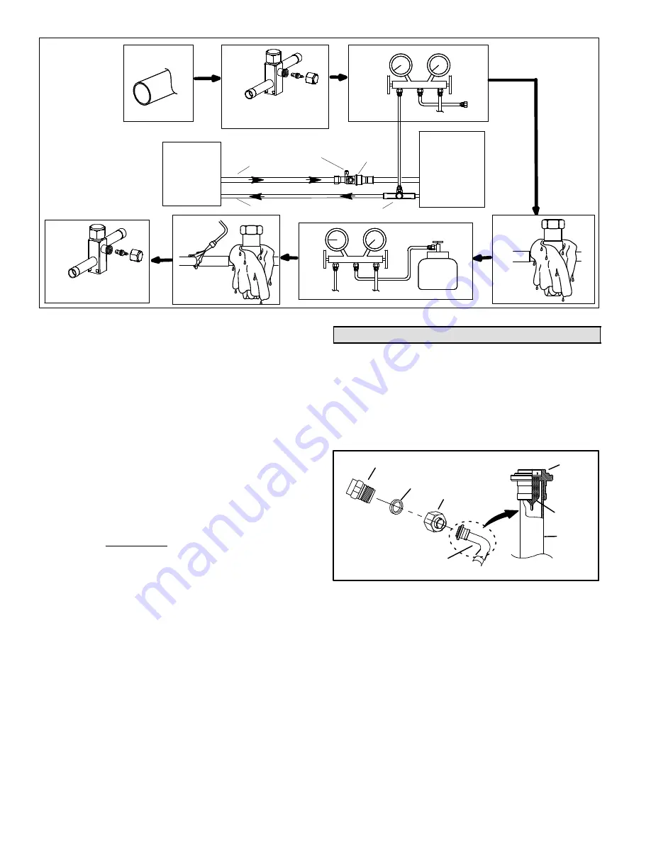
Figure 19. Brazing Connections

2. Remove service cap and core from both the suction

and liquid line service ports.

3. Connect gauge low pressure side to liquid line service

valve.

4. To protect components during brazing, wrap a wet

cloth around the liquid line service valve body and
copper tube stub and use another wet cloth
underneath the valve body to protect the base paint.
Also, shield the light maroon R−410A sticker.

5. Flow regulated nitrogen (at 1 to 2 psig) through the

refrigeration gauge set into the valve stem port
connection on the liquid line service valve and out of
the valve stem port connection on the suction service
valve.

NOTE  The RFCIV or TXV metering device at the indoor
unit will allow low pressure nitrogen to flow through the
system.)

6. Braze the liquid line to the liquid line service valve.

Turn off nitrogen flow. Repeat procedure starting at
paragraph 4 for brazing the suction line to the suction
service valve.

7. After all connections have been brazed, disconnect

manifold gauge set the from service ports, cool down
piping with wet rag and remove all wrappings. Do not
reinstall cores until after evacuation procedures.
Reinstall service caps if desired to close off refrigerant
ports.

Removing Indoor Unit Metering Device11

Remove the existing HCFC−22 refrigerant flow control
orifice or thermal expansion valve from the indoor coil. The
existing indoor unit HCFC−22 metering device is not
approved for use with HFC−410A refrigerant and may
prevent proper flushing.

REPLACEMENT PARTS

If replacement parts are necessary for the indoor unit,
order kit 69J46. The kit includes:

TEFLON RINGS (20)

BRASS NUTS (10)

LIQUID LINE ASSEMBLIES

(INCLUDES STRAINER) (10)

LIQUID LINE ORIFICE HOUSINGS (10)

LIQUID LINE

ASSEMBLY

COPPER
TUBE

PISTON
RETAINER

STRAINER

Figure 20. 69J46 Kit Components

TYPICAL FIXED ORIFICE REMOVAL PROCEDURE

1. On fully cased coils, remove the coil access and

plumbing panels.

2. Remove any shipping clamps holding the liquid line

and distributor assembly.

3. Using two wrenches, disconnect liquid line from liquid

line orifice housing. Take care not to twist or damage
distributor tubes during this process.

Summary of Contents for Signature XP19-024

Page 1: ... Lennox Signature Collection XP19 Series Units HEAT PUMPS 505 331M 06 09 Supersedes 05 09 Table of Contents Shipping and Packing List 1 Unit Dimensions 2 XP19 Heat Pumps 2 General Information 2 Recovering Refrigerant from Existing System 4 Removing Existing Outdoor Unit 5 Positioning New Outdoor Unit 5 Removing Panels 6 New or Replacement Line Set 8 Brazing Connections 9 Removing Indoor Unit Meter...

Page 2: ...ol is known to the State of California to cause cancer Fiberglass wool may also cause respiratory skin and eye irritation To reduce exposure to this substance or for further information consult material safety data sheets available from address shown below or contact your supervisor Lennox Industries Inc P O Box 799900 Dallas TX 75379 9900 XP19 Heat Pumps3 The XP19 Heat Pumps which will also be re...

Page 3: ...rounding or breaking off the wrench or stripping the valve stem recess 1 2 3 4 5 6 7 8 9 10 11 12 1 6 TURN 1 2 3 4 5 6 7 8 9 10 11 12 1 12 TURN Figure 2 Cap Tightening Distances IMPORTANT To prevent stripping of the various caps used the appropriately sized wrench should be used and fitted snugly over the cap before tightening To Access Angle Type Service Port A service port cap protects the servi...

Page 4: ...d wrench to turn an additional 1 6 turn clockwise as illustrated in Figure 2 BALL SHOWN CLOSED SERVICE PORT CORE TO INDOOR UNIT TO OUTDOOR UNIT TO OPEN ROTATE STEM COUNTERCLOCKWISE 90 TO CLOSE ROTATE STEM CLOCKWISE 90 SERVICE PORT SERVICE PORT CAP STEM CAP VALVE STEM OPEN TO LINE SET WHEN VALVE IS CLOSED TO BOTH LINE SET AND UNIT WHEN VALVE IS OPEN Figure 6 Ball Type Service Valve To Open and Clos...

Page 5: ...er to unit and use a recovery machine to recover any refrigerant left in the indoor coil and line set Perform the following task 1 Start the existing HCFC 22 system in the cooling mode and close the liquid line valve 2 Pump as much of the existing HCFC 22 refrigerant with the compressor back into the outdoor unit until you have reached the limitations of the outdoor system Turn the outdoor unit ma...

Page 6: ...e 7 ELEVATING THE UNIT This unit is outfitted with elongated support feet as illustrated in Figure 11 which uses a similar method for elevating the unit LEG DETAIL BASE 2 50 8MM SCH 40 FEMALE THREADED ADAPTER Figure 11 Elevated Slab Mounting using Feet Extenders If additional elevation is necessary raise the unit by extending the length of the unit support feet This may be achieved by using a 2 SC...

Page 7: ... unit as possible Then in a continuous motion S Slightly rotate and guide the lip of top tab inward as illustrated in Figure 13 details A and C then upward into the top slot of the hinge corner post S Rotate panel to vertical to fully engage all tabs S Holding the panel s hinged side firmly in place close the right hand side of the panel aligning the screw holes When panel is correctly positioned ...

Page 8: ...nnections to the indoor unit coil flare or sweat connections Use Lennox L15 sweat non flare series line set or use field fabricated refrigerant lines as listed in Table 2 Table 2 Refrigerant Line Set Model Field Connections Recommended Line Set Liquid Line Suction Line Liquid Line Suction Line L15 Line Set 024 036 048 3 8 10 mm 7 8 22 mm 3 8 10 mm 7 8 22 mm L15 65 15 ft 50 ft 4 6 m 15 m 060 3 8 10...

Page 9: ...O SUCTION LINE WALL STUD LIQUID LINE METAL SLEEVE SUCTION LINE WRAPPED IN ARMAFLEX AUTOMOTIVE MUFFLER TYPE HANGER Figure 18 Refrigerant Line Set Transition from Vertical to Horizontal Brazing Connections10 Use the following procedure to braze the line set to the new air conditioner unit Figure 19 is provided as a general guide for preparing to braze the line set to the air conditioner unit WARNING...

Page 10: ...liquid line to the liquid line service valve Turn off nitrogen flow Repeat procedure starting at paragraph 4 for brazing the suction line to the suction service valve 7 After all connections have been brazed disconnect manifold gauge set the from service ports cool down piping with wet rag and remove all wrappings Do not reinstall cores until after evacuation procedures Reinstall service caps if d...

Page 11: ...liquid line to the indoor unit s liquid line orifice housing Flushing the System12 IMPORTANT The line set and indoor unit coil must be flushed with at least the same amount of clean refrigerant that previously charged the system Check the charge in the flushing cylinder before proceeding IMPORTANT If this unit is being matched with an approved line set or indoor unit coil which was previously char...

Page 12: ...m on the system 5 Close the valve on the inverted HCFC 22 drum and the gauge set valves Pump the remaining refrigerant out of the recovery machine and turn the machine off Installing New Indoor Metering Device13 XP19 units use CTXV for metering refrigerant only This section provides instructions on installing CTXV refrigerant metering device 1 2 3 4 5 6 7 8 9 10 11 12 1 8 TURN 1 2 3 4 5 6 7 8 9 10...

Page 13: ...TION LINE FLARE NUT COPPER FLARE SEAL BONNET MALE BRASS EQUALIZER LINE FITTING FLARE SEAL CAP OR Figure 27 Copper Flare Seal Bonnet Removal IMPORTANT When removing the flare nut ensure that the copper flare seal bonnet is removed 8 Connect the equalizer line from the TXV to the equalizer suction port on the suction line Finger tighten the flare nut plus 1 8 turn 7 ft lbs as illustrated in Figure 2...

Page 14: ...gauges from service ports Evacuating the System15 Evacuating the system of non condensables is critical for proper operation of the unit Non condensables are defined as any gas that will not condense under temperatures and pressures present during operation of an air conditioning system Non condensables and water suction combine with refrigerant to produce substances that corrode copper piping and...

Page 15: ...nder C Reinstall service valve cores by removing manifold hose form service valve Quickly install core with core tool while maintaining a positive system pressure D Replace the stem caps and secure finger tight then tighten an additional one sixth 1 6 of a turn as illustrated in Figure 2 Servicing Units Delivered Void of Charge16 If the outdoor unit is void of refrigerant clean the system using th...

Page 16: ... Type less than 100 30m 18 color coded temperature rating 35ºC minimum more than 100 30m 16 3 Install room thermostat ordered separately on an inside wall approximately in the center of the area and 5 feet 1 5 m from the floor Do not install on an outside wall or where sunlight drafts or vibrations affect it 4 Install low voltage wiring from outdoor to indoor unit and from thermostat to indoor uni...

Page 17: ...alculate the total refrigerant charge Amount specified on nameplate Adjust amount for variation in line set length listed on Table in Figure 31 Additional charge specified per indoor unit match up listed in Tables 4 through 7 Total charge 1 Determine the desired DT Measure entering air temperature using dry bulb A and wet bulb B DT is the intersecting value of A and B in the Table see triangle 2 F...

Page 18: ...ing mode When the outdoor ambient temperature is 60 F 15 C and above Target subcooling values second stage high capacity in Table 8 are based on 70 to 80 F 21 27 C indoor return air temperature if necessary operate heating to reach that temperature range then set thermostat to cooling mode setpoint to 68ºF 20ºC which should call for second stage high capacity cooling When pressures have stabilized...

Page 19: ...X40UHV 036 14 6 0 5 CBX40UHV 042 048 6 6 1 5 CH33 44 48B 12 5 0 13 CH33 48 12 5 0 13 CR33 48 30 5 0 0 CR33 50 60 60 15 4 1 5 Table 8 XP19 036 Continued INDOOR HEAT MATCH UP PUMP Target Subcooling Heating Cooling 5ºF 1ºF Add charge CX34 48 SN before SN 6007K 31 7 0 0 CX34 48 SN 6007K and after 10 8 0 0 CX34 44 48 30 5 0 0 CX34 49 6 6 1 5 CX34 50 60C 12 5 0 13 CX34 60D 8 5 0 15 CX34 62D 6 6 1 5 Tabl...

Page 20: ...ause pressures to vary Temperature of the air entering the outside coil Table 9 HFC 410A Temperature F Pressure Psig F Psig F Psig F Psig F Psig 32 100 8 63 178 5 94 290 8 125 445 9 33 102 9 64 181 6 95 295 1 126 451 8 34 105 0 65 184 3 96 299 4 127 457 6 35 107 1 66 187 7 97 303 8 128 463 5 36 109 2 67 190 9 98 308 2 129 469 5 37 111 4 68 194 1 99 312 7 130 475 6 38 113 6 69 197 3 100 317 2 131 4...

Page 21: ...ign and capacity Lennox System Operation Monitor LSOM 100034 1 20 The diagnostic indicator detects the most common fault conditions in the air conditioning system When an abnormal condition is detected the module communicates the specific condition through its ALERT and TRIP lights The module is capable of detecting both mechanical and electrical system problems IMPORTANT This monitor does not pro...

Page 22: ...ellow Flash Code 1 Long Run Time Compressor is running extremely long run cycles 1 Low refrigerant charge 2 Evaporator blower is not running S Check blower relay coil and contacts S Check blower motor capacitor S Check blower motor for failure or blockage S Check evaporator blower wiring and connectors S Check indoor blower control board S Check thermostat wiring for open circuit 3 Evaporator coil...

Page 23: ...in compressor start wiring or connections S Check wiring and connectors between supply and the compressor S terminal 3 Compressor start winding is damaged S Check compressor motor winding resistance Yellow Flash Code 7 Open Run Circuit Current only in start circuit 1 Open circuit in compressor start wiring or connections S Check wiring and connectors between supply and the compressor R terminal 2 ...

Page 24: ...he auto reset event values for low and high pressure thresholds High Pressure auto reset trip at 590 psig reset at 418 Low Pressure auto reset trip at 25 psig reset at 40 FIVE STRIKE LOCKOUT SAFETY FUNCTION The five strike lockout safety function is designed to protect the unit s compressor from damage The DCB looks for 24VAC on it s Y1 terminal When the Y1 input is see 24VAC then internal control...

Page 25: ...ed sensor or high discharge temperatures Code on board is Discharge Line Temperature Fault and Lockout 2 If the board recognizes five temperature sensor range faults during a single Y1 compressor demand it reverts to a lockout mode and displays the appropriate code The board detects open sensor or out of temperature sensor range This fault is detected by allowing the unit to run for 90 seconds bef...

Page 26: ...fferential which is required to allow a defrost cycle Defrost Mode The following paragraphs provide a detailed description of the defrost system operation DETAILED DEFROST SYSTEM OPERATION Defrost Cycles The demand defrost control board initiates a defrost cycle based on either frost detection or time S Frost Detection If the compressor runs longer than 30 minutes and the actual difference between...

Page 27: ... to the Demand Defrost Control Y1 Active Place a jumper on TEST pins for longer than one second but less than two seconds Clears any short cycle lockout and five strike fault lockout function if applicable No other functions will be executed and unit will continue in the mode it was operating Place a jumper on TEST pins for more than two seconds Clears any short cycle lockout and five strike fault...

Page 28: ...set at 50 F 10 C If the temperature jumper is not installed the default termination temperatureis 90 F 32 C P2 RL 24VAC output for external K229 relay to control blower operation during defrost heat pump inactive mode and a call for second stage gas heat furnace operations C 24VAC system common W Out 24VAC output to furnace control to begin furnace heating operation R 24VAC system power input W In...

Page 29: ...ents OFF ON Low Pressure Discharge Sensor Lockout SLOW Flash OFF High Pressure Fault ON OFF High Pressure Discharge Sensor Lockout SLOW Flash ON Discharge Line Temperature Fault This code detects shorted sensor or high discharge temperatures If the discharge line temperature exceeds a temperature of 300ºF 148ºC during compressor operation the board will de energize the compressor contactor output ...

Page 30: ...etween low and high capacity and replacement is necessary 12 After testing is complete return unit to original set up Homeowner Information Maintenance25 In order to ensure peak performance your system must be properly maintained Clogged filters and blocked airflow prevent your unit from operating at its most efficient level 1 Air Filter Ask your Lennox dealer to show you where your indoor unit s ...

Page 31: ...peration will be similar Temperature Setting Levers Most heat pump thermostats have two temperature selector levers one for heating and one for cooling Set the levers or dials to the desired temperature setpoints for both heating and cooling Avoid frequent temperature adjustment turning the unit off and back on before pressures equalize puts stress on the unit compressor Fan Switch In AUTO or INT ...

Page 32: ...r Cooling Mode Operation Block outdoor coil to maintain a minimum of 375 psig during testing Heating Mode Operation Block indoor coil to maintain a minimum of 375 psig during testing XP19 Start Up and Performance Checklist27 Customer Address Indoor Unit Model Serial Outdoor Unit Model Serial Notes START UP CHECKS Refrigerant Type Rated Load Amps Actual Amps Rated Volts Actual Volts Condenser Fan F...

Reviews: