Page 2
505331M 06/09
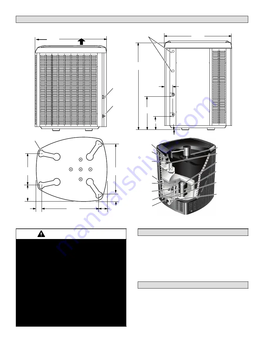
Unit Dimensions −− Inches (mm)2
39−1/2
(1003)
35−1/2
(902)
18−1/2
(470)
8 (203)
1 (25)
4−1/2
(114)
LIQUID LINE
INLET
ELECTRICAL
INLETS
SIDE VIEW
ACCESS VIEW
DISCHARGE AIR
4−5/8
(117)
BASE
16−7/8
(429)
8−3/4
(222)
26−7/8
(683)
3−3/4 (95)
30−3/4
(781)
3−1/8
(79)
SUCTION LINE
INLET
UNIT SUPPORT
FEET
37 (940) [−024, −036]
47 (1194) [−048, −060]
OUTDOOR FAN
RUN
CAPACITOR
TWO−STAGE
COMPRESSOR
COMPRESSOR
TERMINAL
PLUG
LOW
PRESSURE
SWITCH
HIGH
PRESSURE
SWITCH
CONTACTOR
DEFROST
CONTROL
SYSTEM
OPERATION
MONITOR
VAPOR VALVE
AND GAUGE
PORT
DISCHARGE
LINE
REVERSING
VALVE
VAPOR LINE
FILTER DRIER
XP19 PARTS ARRANGEMENT
WARNING
This product and/or the indoor unit it is matched
with may contain fiberglass wool.
Disturbing the insulation during installation,
maintenance, or repair will expose you to fiberglass
wool dust. Breathing this may cause lung cancer.
(Fiberglass wool is known to the State of California
to cause cancer.)
Fiberglass wool may also cause respiratory, skin,
and eye irritation.
To reduce exposure to this substance or for further
information, consult material safety data sheets
available from address shown below, or contact
your supervisor.
Lennox Industries Inc.
P.O. Box 799900
Dallas, TX 75379−9900
XP19 Heat Pumps3
The XP19 Heat Pumps, which will also be referred to in this
instruction as the outdoor unit, uses HFC−410A
refrigerant. This outdoor unit must be installed with a
matching indoor unit and line set as outlined in the
Lennox
XP19
Engineering Handbook
.
This outdoor unit is designed for use in systems that use
check thermal expansion valve (CTXV) refrigerant
metering devices.
General Information4
These instructions are intended as a general guide and do
not supersede local codes in any way. Consult authorities
who have jurisdiction before installation.
When servicing or repairing HVAC components, ensure
the fasteners are appropriately tightened. Table 1 shows
torque values for fasteners.


