Page 24
505331M 06/09
Defrost System21
DEFROST SYSTEM DESCRIPTION
The defrost control board (DCB) measures differential
temperatures to detect when the system is performing
poorly because of ice build−up on the outdoor coil. The
controller self−calibrates when the defrost system starts
and after each system defrost cycle. The DCB
components are illustrated on page 22.
The DCB monitors ambient temperature, outdoor coil
temperature, and total run time to determine when a
defrost cycle is required. The coil temperature probe is
designed with a spring clip to allow mounting to the outside
coil tubing. The location of the coil sensor is important for
proper defrost operation.
NOTE The DCB accurately measures the performance
of the system as frost accumulates on the outdoor coil.
This typically will translate into longer running time
between defrost cycles as more frost accumulates on the
outdoor coil before the board initiates defrost cycles.
DIAGNOSTIC LEDS
The state (Off, On, Flashing) of two LEDs on the DCB
(DS1 [Red] and DS2 [Green]) indicate diagnostics
conditions that are described in Table 15.
DCB PRESSURE SWITCH CONNECTIONS
The unit’s automatic reset pressure switches (LO PS − S87
and HI PS − S4) are factory−wired into the DCB on the
LO−PS and HI−PS terminals, respectively.
Low Pressure Switch (LO−PS)
When the low pressure
switch trips, the DCB will cycle off the compressor, and the
strike counter in the board will count one strike. The low
pressure switch is ignored under the following conditions:
S
during the defrost cycle and 90 seconds after the
termination of defrost
S
when the average ambient sensor temperature is
below 15° F (−9°C)
S
for 90 seconds following the start up of the compressor
S
during TEST mode
High Pressure Switch (HI−PS)
When the high pressure
switch trips, the DCB will cycle off the compressor, and the
strike counter in the board will count one strike.
DCB PRESSURE SWITCH EVENT SETTINGS
The following pressures are the auto reset event values for
low and high pressure thresholds:
High Pressure
(auto reset) − trip at 590 psig; reset at 418.
Low Pressure
(auto reset) − trip at 25 psig; reset at 40.
FIVE−STRIKE LOCKOUT SAFETY FUNCTION
The five−strike lockout safety function is designed to
protect the unit’s compressor from damage. The DCB
looks for 24VAC on it’s Y1 terminal. When the Y1 input is
see 24VAC, then internal control logic of the DCB will do
the following:
S
Count any HI−PS and LO−PS pressure switch trips
(open and close). Individual HI−PS and LO−PS trips
are added together for the total number of trips
counted by the DCB.
S
Up to four pressure switch trips are allowed in a single
thermostat demand without locking out the DCB. If the
thermostat demand satisfies before a fifth pressure
switch trip, the DCB will reset the five−strike counter to
zero.
S
If either pressure switch opens for a fifth time during
the current Y1 input state, the DCB will enter a lockout
condition.
The system will require servicing to determine the cause of
the pressure switch condition. Once the condition has
been rectified, use the following procedure to reset the
DCB
.
Low Ambient Thermostat Pins
− P3 provides selecting of
the Y2 compressor lock−in temperature.
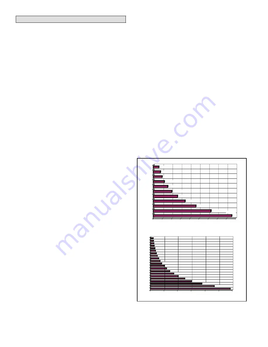
DEFROST SYSTEM SENSORS
Sensors connect to the DCB through a field-replaceable
harness assembly that plugs into the board. Through the
sensors, the DCB detects outdoor ambient, coil, and
discharge temperature fault conditions. As the detected
temperature changes, the resistance across the sensor
changes. Figure 34 shows how the resistance varies as
the temperature changes for both type of sensors. Sensor
resistance values can be checked by ohming across pins
shown in Table 34.
Ambient and Coil Sensor
Discharge Sensor
RESISTANCE (OHMS)
RESISTANCE (OHMS)
TEMPERA
TURE (ºF)
TEMPERA
TURE (ºF)
5750
7450
9275
11775
15425
19975
26200
34375
46275
62700
200
325
250
425
600
825
1175
1700
2500
3750
5825
100
90
80
70
60
50
40
30
20
10
0
300
280
260
240
220
200
180
160
140
120
100
10000
30000
50000
70000
90000
1000
2000
5000
4000
6000
3000
4650
3000
2025
1400
1000
700
225
275
375
500
85300
Figure 34. Temperature/Resistance Chart


