Page 28
505331M 06/09
P2
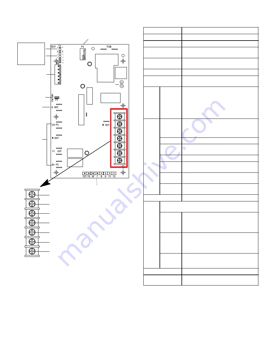
24V TERMINAL STRIP
CONNECTIONS
DS1 AND DS2
PRESSURE
SWITCH
CIRCUIT
CONNECTIONS
NOTE Component locations may vary by board manufacturer.
P4
REVERSING
VALVE
P5
P3
DEMAND DEFROST CONTROL BOARD
A10822
Diagnostic LED descriptions are listed in Table 15.
DIAGNOSTIC LEDs
P6
P1
DEFROST
TERMINATION
PIN SETTINGS
TEST PINS
RL
W OUT
C
R
W IN
O
Y1
Table 14. Demand Defrost Control A108
Inputs/Outputs and Jumper Settings
ID
Description
O OUT
24VAC output connection for reversing valve.
LO−PS
Connection for low−pressure switch
W−OUT
24VAC output for second−stage (gas heat)
furnace connection
Y1
24VAC common output, switched to enable
compressor contactor.
H1−PS
Connection for high−pressure switch.
FAN
240 VAC line voltage connection for condenser
fan.
P1
50
70
90
100
Defrost Termination Settings: Seven position
square pin header. The defrost termination
temperature is measured by the defrost coil
sensor. The jumper termination pin is factory
set at 50°F (10°C). If the temperature jumper is
not installed, the default termination
temperature is 90°F (32°C).
P2
RL
24VAC output for external K229 relay to control
blower operation during defrost, heat pump
inactive mode, and a call for second−stage (gas
heat) furnace operations.
C
24VAC system common
W Out
24VAC output to furnace control to begin
furnace heating operation.
R
24VAC system power input
W In
24VAC thermostat input for second stage (gas
heat) furnace operation
O
24VAC thermostat input for reversing valve
operation
Y1
24VAC thermostat input for first−stage
compressor operation
P3
Not used.
P4
Six position square pin header. P4 provides connections for
the temperature sensors.
COIL
(BROWN)
(PIN 1) Ground connection for outdoor coil
temperature sensor.
(PIN 2) Connection for outdoor coil temperature
sensor.
AMB
(BLACK)
(PIN 3) Ground connection for outdoor ambient
temperature sensor.
(PIN 4) Connection for outdoor ambient
temperature sensor.
DIS
(YELLOW)
(PIN 5 and PIN 6) Harness resistor fault 10K
resistor. 10K resistor built into wiring harness
connected to the DIS connector.
P5
For factory test.
P6
Eight−position header. Provides connections
for the factory test.


