background image

Page 29

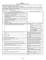
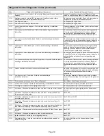
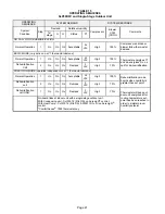
6. Primary Limit Control (S10)

Figure 15 shows the primary limit (S10) used on SLP98DFV
units located in the heating vestibule panel.  When excess heat
is sensed in the heat exchanger, the limit will open. Once the
limit opens, the furnace control energizes the supply air
blower and de-energizes the gas valve. The limit automati­
cally resets when unit temperature returns to normal. The
switch is factory set and cannot be adjusted. In the event of
restricted air flow, the integrated control will reduce firing
rate and indoor blower airflow in 10% increments until a sus­
tainable air flow is reached. If the furnace reaches 35% fir­
ing rate, and adequate air flow is not available, the furnace
will shutdown and enter one hour watchguard. For limit re­
placement remove wires from limit terminals and rotate limit
switch 90 degrees. Slowly remove from the vestibule panel.

FIGURE 15

Primary Limit Location and Heat Exchanger

install limit face down

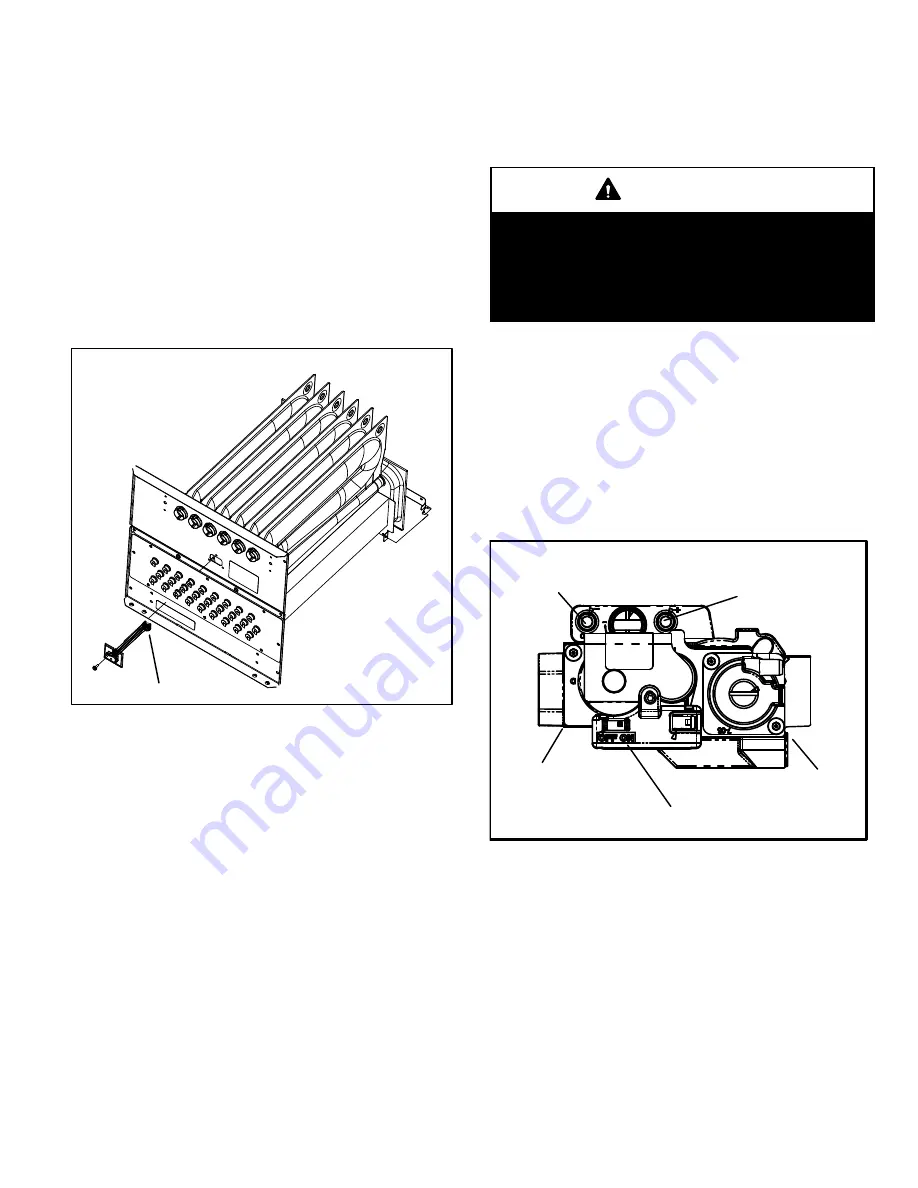
7. Gas Valve (GV1)

The SLP98DFV uses a variable capacity gas valve (figure
46) and is applicable for two-stage, three-stage or variable
capacity settings. See “Thermostat selection modes” in the
integrated control section (section A- subsection 4.) for
more details The valve is internally redundant to assure
safety shut-off. If the gas valve must be replaced, the same
type valve must be used.

A 24VAC 2-pin plug and gas control switch are located on  the
valve. 24V applied to the pins enables valve operation.

Inlet and outlet pressure taps are located on the valve.

LPG  change over kits are available from Lennox. Kits include

burner orifices and an LP gas valve.

DANGER

Danger of explosion.

There are circumstances in which odorant used with
LP/propane gas can lose its scent.  In case of a leak,
LP/propane gas will settle close to the floor and may
be difficult to smell. An LP/propane leak detector
should be installed in all LP applications.

The burner box is sealed and operates under a negative

pressure. A pressure hose is connected from the burner box

to the gas valve. The gas valve senses the pressure in the

burner box and uses that to set the maximum manifold pres­

sure while the pressure switch with pressure conditioning

device adjusts the gas flow. This will compensate for differ­

ent vent configurations which can greatly affect the rate of

the unit.

GAS VALVE

NEGATIVE AIR

PRESSURE PORT

POSITIVE AIR

PRESSURE PORT

MANIFOLD

PRESSURE TAP

INLET

OUTLET

SUPPLY

PRESSURE

TAP

GAS VALVE SHOWN IN THE ON POSITION

FIGURE 16

Summary of Contents for SLP98DF070XV36B

Page 1: ...ions only and do not supersede or replace local or state codes In the absence of local or state codes the guidelines and procedures outlined in this manual except where noted are recommendations only and do not consti tute code TABLE OF CONTENTS Specifications Page 2 Optional Accessories Page 3 Blower Data Page 4 I Unit Components Page 8 II icomfort Wi Fi Thermostat Page 33 III Placement and Insta...

Page 2: ... field provided 1 Annual Fuel Utilization Efficiency based on DOE test procedures and according to FTC labeling regulations Isolated combustion system rating for non weatherized furnaces SPECIFICATIONS Gas Heating Performance Model No SLP98DF090XV60C SLP98DF110XV60C 1 AFUE 97 5 97 5 Maximum Input Btuh 88 000 110 000 Output Btuh 85 000 107 000 Temperature rise range F 50 80 50 80 Gas Manifold Press...

Page 3: ...r 3 in 51W11 51W11 Canada 2 2 1 2 or 3 in 51W12 51W12 Wall Close Couple US 2 in 22G44 3 in 44J40 44J40 Wall Close Couple WTK Canada 2 in 30G28 3 in 81J20 81J20 Roof 2 in 15F75 15F75 Wall Ring Kit 2 in 15F74 15F74 Roof Termination Flashing Kit 2 flashings 3 in 44J41 44J41 VENTING 4 Left Side Vent Kit 2 or 3 in 87W73 87W73 1 Remote Outdoor Sensor may be used with an iComfort enabled outdoor unit for...

Page 4: ...emand at 70 input W2 demand at 100 input No delay between stages icomfort Touch Communicating Thermostat Variable Rate Capacity Mode furnace automatically adjusts firing rate based on first and second stage cycle times 35 60 80 100 four stage with time delays in between Cool Mode Available Cooling Blower Performance table First stage COOL two stage air conditioning units only is approximately 70 o...

Page 5: ...e same second stage COOL speed position Continuous Fan speeds are approximately 28 38 70 and 100 DIP switch selectable of the same second stage COOL speed position minimum 450 cfm Lennox Harmony III Zoning System Applications Minimum blower speed is 380 cfm SLP98DF090V48C and 450 cfm SLP98DF090V60C COOLING BLOWER PERFORMANCE Cooling Adjust CFM Selections Blower Speed Selections First Stage Cool Sp...

Page 6: ...first and second stage cycle times W1 demand at 70 input W2 demand at 100 input No delay between stages icomfort Touch Communicating Thermostat Variable Rate Capacity Mode furnace automatically adjusts firing rate based on first and second stage cycle times 35 60 80 100 four stage with time delays in between Cool Mode Available Cooling Blower Performance table First stage COOL two stage air condit...

Page 7: ...NEL COMBUSTION AIR INDUCER BLOWER ACCESS PANEL BLOWER ASSEMBLY Variable Speed Blower Motor Is Hidden BAG ASSEMBLY CONTROL BOX includes variable capacity integrated control transformer circuit breaker and door switch PRIMARY LIMIT SLP98DFV PARTS ARRANGEMENT ...

Page 8: ... pressing the button on the face See figure 3 FIGURE 3 CIRCUIT BREAKER CB8 PRESS TO RESET WARNING Shock hazard Disconnect power before servicing Integrated control is not field repairable If control is inoperable simply replace entire control Can cause injury or death Unsafe operation will re sult if repair is attempted 4 Integrated Control A92 SLP98DFV units are equipped with the Lennox SureLight...

Page 9: ...ted accordingly to provide the appropriate airflow at any rate On the initial call for low fire the furnace will operate at 35 and will remain there until the heat call is satisfied or a call for high fire is initiated If there is a call for high fire the rate will increase by 10 if the current rate is above 60 However if the current rate is below 60 the rate will in crease to 70 After this initia...

Page 10: ...DS DEHUMIDIFICATION SIGNAL W2 HEAT DEMAND FROM 2ND STAGE T STAT W1 HEAT DEMAND FROM 1ST STAGE T STAT R CLASS 2 VOLTAGE TO THERMOSTAT G MANUAL FAN FROM T STAT C THERMOSTAT SIGNAL GROUND CONNECTED TO TRANSFORMER GRD TR CHASIS GROUND GRD Y1 THERMOSTAT 1ST STAGE COOL SIGNAL Y2 THERMOSTAT 2ND STAGE COOL SIGNAL O THERMOSTAT SIGNAL TO HEAT PUMP REVERSING VALVE H 24V HUMIDIFIER OUTPUT DO NOT CONNECT TO CO...

Page 11: ...Page 11 FIGURE 5 SLP98DFV INTEGRATED CONTROL CONFIGURATION GUIDE ...

Page 12: ... be adjusted by moving switches 4 and 5 on the integrated control The unit is shipped from the facto ry with a blower off delay of 90 seconds The blower off delay affects comfort and is adjustable to satisfy individual applications Adjust the blower off delay to achieve a supply air temperature between 90 and 110 F at the exact mo ment that the blower is de energized Longer off delay set tings pro...

Page 13: ...set at option A which has the great est effect on blower motor performance Table 8 provides the cooling mode blower speed ramping options that will re sult from different switch settings The cooling mode blower speed ramping options are detailed below TABLE 8 Cooling Mode Blower Speed Ramping Ramping Option Switch 12 Switch 13 A Factory Off Off B On Off C Off On D On On Ramping Option A Factory Se...

Page 14: ... 10 provides the heating mode blower speeds that will result from different switch settings Figure 6 indicates the effect the DIP switch set tings tables 20 21 above have upon the heating airflow at various furnace firing rates Refer to blower tables at the front of this manual for corre sponding cfm values TABLE 10 High Heat Blower Speeds Thermostat Demand Blower Speed Adjust ments DIP SWITCH SET...

Page 15: ...st be pressed a second time while c is flashing to confirm command to delete codes Press the button until a solid is displayed to exit the Error Code Recall mode Field Test Mode Use the diagnostic push button to scroll through the menu as described above Release the button when the LED flashes to select the Field Test mode While in the Field Test mode the technician can D Initiate furnace ignition...

Page 16: ...o change blinking remain in field test mode Solid exit field test mode Solid c start pressure switch calibration TABLE 13 Field Test Menu Options These options are displayed when the button is used in diagnostic recall mode DISPLAY ACTION when button released No change displaying error history remain in diagnostic recall mode Solid 3 horizontal bars exit diagnostic recall mode Solid c clear error ...

Page 17: ...10 second period During that period hold push button until code stops blinking disappear for 2 seconds Integrated control will store code in memory and will automatically exit Field Test Mode and reset If second period expires or push button is held less than five seconds control will automatically exit Field Test Mode and go into IDLE mode without storing unit size code If this happens programmin...

Page 18: ...thermostat through set up 4 Go to setup system devices thermostat edit then push reset 5 Go to setup system devices thermostat edit then push resetAll E 105 Device communication problem No other devices on BUS Communication system Equipment is unable to communicate Check for mis wire and loose connections and check for a high voltage source of noise close to the system welder etc E 110 Low line vo...

Page 19: ...ct operation and restriction E 227 Low pressure switch open during trial for ignition or run mode Refer to trouble shooting in installation instruction Check inches of water column pressure during operation of low pressure switch on heat call measure inches of water column of operating pressure inspect vent and combustion air inducer for correct operation and restric tion E 228 Unable to perform s...

Page 20: ...per configuration in installation instruc tions Alarm is just a warning The system operation is not impacted at all and alarm would clear when Commissioning is exited E 331 Global network connection Communication link problem For Future Use E 347 No 24 Volt output on Y1 to C with non communicating outdoor unit Y1 relay Stage 1 failed Pilot relay contacts did not close or the relay coil did not ene...

Page 21: ...e humidification Dehumidification Call 2 On On On Demand 0 VAC High 70 PRECISION MODE operates independent of a Y1 thermostat demand Normal Operation 1 On On On Acceptable 24 VAC High 100 Dehumidification mode begins when humidity is greater than set point Dehumidification call 2 On On On Demand 0 VAC High 70 Dehumidification call ONLY 1 On On On Demand 0 VAC High 70 Thermostat will keep out door ...

Page 22: ...igh 70 Thermostat will keep out door unit energized after cooling temperature set point has been reached in order to maintain room humidity setpoint ROOM THERMOSTAT CALLS FOR FIRST AND SECOND STAGE COOLING BASIC MODE only active on a Y1 thermostat demand Normal Operation 1 On On On On Acceptable 24 VAC High 100 Thermostat energizes 2nd stage and de ener gizes D on a call for de humidification Dehu...

Page 23: ...itions inside the motor such as motor work load SLP98DFV BLOWER MOTOR COMPONENTS FIGURE 8 STATOR WINDINGS OUTPUT SHAFT BEARING The controller uses sensing devices to sense what position the rotor is in at any given time By sensing the position of the rotor and then switching the motor windings on and off in se quence the rotor shaft turns the blower All SLP98DFV blower motors use single phase powe...

Page 24: ...out Reset controller by momentarily turning off power to unit The DC filter capacitors inside the controller are connected electrically to the motor supply wires The capacitors take approximately 5 minutes to discharge when the disconnect is opened For this reason it is necessary to wait at least 5 minutes after turning off power to the unit before attempt ing to service motor DANGER Disconnect po...

Page 25: ...ote Do not apply 24V to pins 2 and 4 on P49 Doing so will cause permanent damage to the motor 6 Motor should run at 75 7 Test is complete Remove jumpers and reconnect plugs Another option is to use the TECMate PRO motor tester with the 16 to 4 pin adaptor The use of the TECMate PRO isolates the motor from the integrated control Follow the instructions provided with the kit If the motor runs do not...

Page 26: ...T A Measure the resistance between each of the three motor leads 3 pin plug and the unpainted part of the end shield If the winding resistance to ground is 100k ohms replace the motor and control module If the resistance to ground is 100k the motor windings are fine Proceed to Test B Test A FIGURE 12 TEST B Use an ohmmeter to measure the motor phase to phase re sistance by checking these combinati...

Page 27: ...ical switches The limit is a N C SPST manual reset limit connected in series with the primary limit S10 When S47 senses rollout the circuit breaks and the integrated control immediately stops ignition and closes the gas valve If unit is running and flame rollout is detected the gas valve will close and integrated control will be disabled Rollout can be caused by a blocked heat exchanger flue or la...

Page 28: ...Page 28 FIGURE 14 Burner Box Assembly Burner Assembly Rollout Switch Ignitor Flame Sensor Burner Box Front Cover remove screw to open cover Sight Glass Intake Air Collar Gas Valve ...

Page 29: ...the integrated control section section A subsection 4 for more details The valve is internally redundant to assure safety shut off If the gas valve must be replaced the same type valve must be used A 24VAC 2 pin plug and gas control switch are located on the valve 24V applied to the pins enables valve operation Inlet and outlet pressure taps are located on the valve LPG change over kits are availa...

Page 30: ...he vent calibration sequence establishes furnace operat ing parameters in a specific installation The integrated con trol runs the calibration and may be repeated as necessary to maintain proper furnace operation Prior to calibration all duct work and returns vent pipe and condensate trap primed must be connected If calibration is successful the data is stored in memory and will be used to determi...

Page 31: ...hould be taken at the pressure switch Lack of differential usually indicates problems in the in take or exhaust piping but may indicate problems in the heat exchanger condensing coil header boxes com bustion inducer or other components The differential pressure is the difference in pressure mea sured across the cold end header box orifice FIGURE 18 1 Remove thermostat demand and allow unit to cycl...

Page 32: ...ressure differential across the CAI orifice difference in the channel and cold end header box See table 19 for orifice size per unit If replacement is necessary the gaskets used to seal the box to the vestibule panel and the CAI to the box must also be replaced TABLE 19 SLP98DFV Unit C A I Orifice Size 070 1 5 070 6 9 070 10 and later 0 780 0 833 0 775 090 1 9 090 10 and later 0 920 0 890 110 1 9 ...

Page 33: ...lamp Tubing Exhaust Elbow Exhaust Coupling Blower Deck Seal Pipe Clamp Exhaust Pipe Intake Air Pipe Cold End Header Box Combustion Air Inducer CAI Exhaust Connector with Alignment Tabs Drain Cap Combustion Air Inducer Cold End Header Box Vent Pipe Assembly ...

Page 34: ...mfort Wi Fi Thermostat icomfortt Enabled SLP98DFV Indoor Furnace icomfortt Enabled Outdoor Air Conditioner or Heat Pump icomfortt ENABLED SLP98DFV FURNACE icomfortt ENABLED OUTDOOR AIR CONDITIONING OR HEAT PUMP UNIT OPTIONAL OUTDOOR AIR SENSOR OPTIONAL DISCHARGE AIR SENSOR CLIP Y1 TO Y2 FOR TWO STAGE OPERATION icomfort Wi Fi THERMOSTAT Indoor Unit Controller Outdoor Unit IcomfortWi Fi thermostat S...

Page 35: ...IR SENSOR FOR USE WITH HU MIDIFIER IF NOT ALREADY IN THE SYSTEM FOR OTHER FUNCTIONS BUILT INTO ALL icomfortt OUTDOOR UNITS icomfortt ENABLED SLP98DFV FURNACE HEPA BYPASS FILTER X2680 HEPA INTERLOCK KIT PASS INDOOR BLOWER MOTOR COMMON WIRE THROUGH CURRENT LOOP SEE HEPA INTERLOCK KIT FOR INSTALLATION DE TAILS LVCS VENTILATION CONTROL SYSTEM SEE LVCS VENTILATION INSTRUCTIONS FOR DAMPER SENSOR WIRING ...

Page 36: ...d Fittings ULCS636 PVC CPVC Solvent Cement ABS to PVC or CPVC Transition Cement POLYPROPYLENE VENTING SYSTEM ULC S636 PolyPro by Duravent ULC S636 InnoFlue by Centrotherm ULC S636 CAUTION Solvent cements for plastic pipe are flammable liq uids and should be kept away from all sources of igni tion Do not use excessive amounts of solvent ce ment when making joints Good ventilation should be maintain...

Page 37: ...ANGER OF EXPLOSION Fumes from PVC glue may ignite during system check Allow fumes to dissipate for at least 5 minutes before placing unit into operation 1 Measure and cut vent pipe to desired length 2 Debur and chamfer end of pipe removing any ridges or rough edges If end is not chamfered edge of pipe may remove cement from fitting socket and result in a leak ing joint 3 Clean and dry surfaces to ...

Page 38: ...rt PVC pipe inside the stack until the end is even with the top or outlet end of the metal stack CAUTION The exhaust vent pipe operates under positive pres sure and must be completely sealed to prevent leak age of combustion products into the living space Vent Piping Guidelines NOTE Lennox has approved the use of DuraVent and Centrotherm manufactured vent pipe and terminations as an option to PVC ...

Page 39: ... of horizontal run is mandatory for drainage NOTE Exhaust pipe MUST be glued to furnace exhaust fittings NOTE Exhaust piping should be checked carefully to make sure there are no sags or low spots Use the following steps to correctly size vent pipe diameter IMPORTANT Do not use screens or perforated metal in exhaust or intake terminations Doing so will cause freeze ups and may block the terminatio...

Page 40: ...8 n a 127 108 83 9 51 29 100 53 122 103 78 10 46 24 95 48 117 98 73 Standard Termination Elevation 4501 7500 Number Of 90 Elbows Used 2 Pipe 2 1 2 Pipe 3 Pipe Model Model Model 070 090 110 070 090 110 070 090 110 1 66 69 14 115 93 43 137 143 118 2 61 64 9 110 88 38 132 138 113 3 56 59 n a 105 83 33 127 133 108 4 51 54 100 78 28 122 128 103 5 46 49 95 73 23 117 123 98 6 41 44 90 68 18 112 118 93 7 ...

Page 41: ...06 99 74 10 38 22 85 44 101 94 69 Concentric Termination Elevation 4501 7500 Number Of 90 Elbows Used 2 Pipe 2 1 2 Pipe 3 Pipe Model Model Model 070 090 110 070 090 110 070 090 110 1 58 67 12 105 89 39 121 114 114 2 53 62 7 100 84 34 116 109 109 3 48 57 n a 95 79 29 111 104 104 4 43 52 90 74 24 106 99 99 5 38 47 85 69 19 101 94 94 6 33 42 80 64 14 96 89 89 7 28 37 75 59 n a 91 84 84 8 23 32 70 54 ...

Page 42: ...haust pipe When transitioning up in pipe size use the shortest length of 2 PVC pipe possible NOTE Exhaust pipe and intake pipe must be the same diameter 2 FIGURE 26 TYPICAL AIR INTAKE PIPE CONNECTIONS 2 2 TRANSITION 3 TRANSITION 2 3 TRAP Use only the factory supplied trap Trap can be installed on either side of cabinet within 5 ft of the furnace TOP VIEW Exhaust Air Intake 2 2 2 When transitioning...

Page 43: ...ove paved sidewalk or paved driveway located on public property Clearance under veranda porch deck or balcony 12 7 feet 2 1m 3 feet 9m within a height 15 feet 4 5m above the meter regulator assembly 3 feet 9m 6 inches 152mm for appliances 10 000 Btuh 3kw 9 inches 228mm for ap pliances 10 000 Btuh 3kw and 50 000 Btuh 15 kw 12 inches 305mm for ap pliances 50 000 Btuh 15kw 6 inches 152mm for applianc...

Page 44: ...door ambient temperature and are above 32 degrees F 0 C are to be considered conditioned spaces IMPORTANT Do not use screens or perforated metal in exhaust ter minations Doing so will cause freeze ups and may block the terminations IMPORTANT For Canadian Installations Only In accordance to CSA International B149 installation codes the minimum allowed distance between the combustion air intake inle...

Page 45: ...de of the structure and the exhaust on another side figure 30 You may exit the exhaust out the roof and the intake out the side of the structure figure 31 2 Intake and exhaust pipes should be placed as close to gether as possible at termination end refer to illustra tions Maximum separation is 3 76mm on roof ter minations and 6 152mm on side wall terminations NOTE When venting in different pressur...

Page 46: ... Roof Terminated Exhaust Pipe Furnace Exiting Exhaust and Intake Vent different pressure zones Inlet Air Minimum 12 in 305 MM above grade or snow accumulation 7 If intake and exhaust piping must be run up a side wall to position above snow accumulation or other ob structions piping must be supported At least one bracket must be used within 6 from the top of the el bow and then every 24 610mm as sh...

Page 47: ... 227 mm Min 12 305 mm Min 16 405 mm Max 6 152 mm Max 6 152 mm Min 24 610 mm Max 9 227 mm Min 12 305 mm Min 20 508 mm Max 6 152 mm Max Intake Elbow WALL SUPPORT B A D E B D E A ALTERNATE TERMINATIONS TEE FORTY FIVE DEGREE ELBOWS ONLY D C 12 1 2 E B A 1 The exhaust termination tee should be connected to the 2 or 3 PVC flue pipe as shown in the illustration Do not use an accelerator in applications t...

Page 48: ...0G28 or 81J20 Inches mm Side View 12 305mm Min above grade or average snow ac cumulation optional intake elbow FIGURE 35 DIRECT VENT CONCENTRIC ROOFTOP TERMINATION 71M80 69M29 or 60L46 US 41W92 or 41W93 Canada Minimum Above Average Snow Accumulation SHEET METAL STRAP Clamp and sheet metal strap must be field installed to support the weight of the termination kit FLASHING Not Furnished CLAMP FIELD ...

Page 49: ...e a large flat head screw driver or a 1 2 drive socket extension and remove plug Install provided 3 4 NPT street elbow fitting into cold end header box Use Teflon tape or appropriate pipe dope 3 Install the cap over the clean out opening at the base of the trap Secure with clamp See figure 44 3 4 drain connection or 45 1 2 drain connection 4 Install drain trap using appropriate PVC fittings glue a...

Page 50: ...rain Line vent required IMPORTANT When combining the furnace and evaporator coil drains together the A C condensate drain outlet must be vented to relieve pressure in order for the furnace pressure switch to operate properly FIGURE 42 SLP98DFV with Evaporator Coil Using a Common Drain Field Provided Vent 1 min 2 max above condensate drain Evaporator Drain Line vent required Condensate Drain Connec...

Page 51: ...t Condensate Drain Connection In Unit Vent To Drain Condensate Drain Connection In Unit Optional Condensate Drain Connection OptionalDrainPipingFromTrap DrainTrapAssembly Furnished DrainTrap Assembly with 1 2 inch Piping DrainTrap Assembly with 3 4 inch Piping 1 2 inch 3 4 inch 1 25 mm Min 2 50 mm Max Above Top Of Condensate Drain Connection In Unit 1 25 mm Min 2 50 mm Max Above Top Of Condensate ...

Page 52: ...ly for 3 4 inch Drain Pipe 90 Street Elbow 1 2 inch PVC Not Furnished Condensate Drain Connection In Unit Adapter 1 2 inch slip X 1 2 inch mpt Not Furnished Condensate Drain Connection In Unit Vent To Drain Condensate Drain Connection In Unit Drain Trap Assembly with 3 4 inch Piping Vent To Drain Furnished Optional Condensate Drain Connection Optional Drain Piping From Trap Drain Trap Assembly Fur...

Page 53: ...ctivate the heating demand and again wait for the combustion air inducer to stop At this point the trap should be primed with sufficient wa ter to ensure proper condensate drain operation BEFORE PLACING THE UNIT INTO OPERATION the unit smell all around the furnace area for gas Be sure to smell next to the floor because some gas is heavier than air and will settle on the floor The gas valve on the ...

Page 54: ... fer to the SLP98DFV Installation Instruction B Gas Piping CAUTION If a flexible gas connector is required or allowed by the authority that has jurisdiction black iron pipe shall be installed at the gas valve and extend outside the furnace cabinet The flexible connector can then be added between the black iron pipe and the gas supply line WARNING Do not over torque 800 in lbs or under torque 350 i...

Page 55: ...nd install a field provided barbed fitting Connect measuring device connection to barbed fitting to measure manifold pressure 2 Tee into the gas valve regulator vent hose and connect measuring device connection 3 Start unit on low heat 35 rate and allow 5 minutes for unit to reach steady state 4 While waiting for the unit to stabilize notice the flame Flame should be stable and should not lift fro...

Page 56: ...ing Red and Black Tubing or Red Tubing F Proper Combustion Furnace should operate minimum 15 minutes with correct manifold pressure and gas flow rate before checking com bustion Take combustion sample beyond the flue outlet and compare to the tables below TABLE 30 High Fire SLP98DFV Unit CO2 For Nat CO2 For L P 070 6 5 9 0 7 7 10 2 090 110 The maximum carbon monoxide reading should not exceed 100 ...

Page 57: ...e combustion air pressure switch is factory set and re quires no adjustment TABLE 32 Conversion Kit Requirements Model Input Size LP Propane Kit High Altitude Pressure Switch Kit 0 10 000 0 3048 m 0 7 500 0 2286 m 7 501 10 000 2287 3048m 070 65W77 Not required 14T67 090 110 TABLE 33 Manifold and Operating Signal Pressures in inches 0 7500 ft 0 2286 m SLP98 Firing Rate Manifold Pressure Nat Gas Man...

Page 58: ...External static pressure drop must not be more than 0 8 W C in the heating mode and must not exceed 1 0 W C in the cooling mode 5 Seal the hole when the check is complete VII MAINTENANCE WARNING ELECTRICAL SHOCK FIRE OR EXPLOSION HAZARD Failure to follow safety warnings exactly could result in dangerous operation serious injury death or prop erty damage Improper servicing could result in dangerous...

Page 59: ...ine connected to gas valve Re move the burner box cover and remove gas valve manifold assembly 5 Remove sensor wire from sensor Disconnect 2 pin plug from the ignitor 6 Disconnect wires from flame roll out switches 7 Remove four burner box screws at the vestibule panel and remove burner box Set burner box assembly aside NOTE If necessary clean burners at this time Follow procedures outlined in Bur...

Page 60: ...lve 42 Replace the blower compartment access panel 43 Refer to instruction on verifying gas and electrical con nections when re establishing supplies 44 Follow lighting instructions to light and operate furnace for 5 minutes to ensure that heat exchanger is clean and dry and that furnace is operating properly 45 Replace heating compartment access panel Cleaning the Burner Assembly 1 Turn off elect...

Page 61: ...ener gized at ignition speed which is approximately the same as the inducer speed at 70 percent firing rate 2 Once the control receives a signal that the low fire pressure switch has closed the combustion air inducer begins a 15 second pre purge in ignition speed 3 After the pre purge is complete a 20 second initial ig nitor warm up period begins The combustion air in ducer continues to operate at...

Page 62: ...y factory set at 7 minutes adjustable to 12 minutes 5 If the heating demand continues beyond the second stage on delay the integrated control energizes the combustion air inducer at 70 percent speed The in door blower motor is adjusted to a speed which matches the target rate A fixed 10 minute third stage on delay is initiated 6 If the heating demand continues beyond the third stage on delay the i...

Page 63: ...Trial Wait For Ignition Stabilization Delay Post Purge 20Seconds Soft Lockout Error Code Flashes YES NO NO YES Call For Heat Ends NO YES YES NO C A L L F O R 1 S T S T A G E H E A T 3A 2 1 1 OR Call For Heat NO 4 Calibrations Attempted Calibration Successful Wait 5 minutes NO NO Soft Lockout Error Code Flashes YES YES YES 2 1 1 2 Set Target Firing Rate Based on Thermostat Signals Present SOF T LOC...

Page 64: ...O Error Code Flashes NO YES Wait 5 Minutes 3A 2 1 2 1 System will always light at 70 even if 2nd stage call for heat is in place If the high pressure switch does not close within 5 attempts the system will operate at low fire for the remainder of the call for heat at request Combustion Air Inducer ON 100 Rate Speed Increase Combustion Air Inducer Speed if Not at 100 Rate Speed Adjust Indoor Blower...

Page 65: ...ostat 1 4 3A 3B YES OR Combustion Air Inducer switched to 70 rate speed Adjust Indoor Blower to appropiate speed Combustion Air Inducer OFF after 20 Second Post Purge Indoor Blower OFF after OFF Delay RUN MODE 2 STAGE THEREMOSTAT 1ST OR 2ND STAGE CALL FOR HEAT ALL INPUTS MONITORED LIMIT PRESSURE CALL FOR HEAT COOL FLAME LEVEL RUN MODE SINGLE STAGE THERMOSTAT ALL INPUTS MONITORED LIMIT PRESSURE CAL...

Page 66: ... Code Flashes YES NO NO YES Call For Heat Ends NO YES YES NO C A L L F O R H E A T 3B 1 4 Move to Mid Firing Rate and High Firing Rate after 2nd and 3rd Stage Delays based on DI P Switch selections Pressure Switch Calibration Call For Heat NO 4 Calibrations Attempted Calibration Successful Wait 5 minutes NO NO Soft Lockout Error Code Flashes YES YES YES SOFT LOCKOUT IS RESE T AUTOMATICAL LYAFTER O...

Page 67: ... mode High Cooling mode High Cooling mode Per Ramping Profile NO NO YES NO 5 1 2 1 2 2 2 1 Indoor Blower On After 2 second delay Energize Indoor Blower Per Ramping Profile Energize Indoor Blower Maintain Indoor Blower Maintain Indoor Blower at De Energize Indoor Blower 2nd stage cooling operation requires a 2 stage thermostat a 2 stage cooling system and jumpers W915 must be be cut The control wil...

Page 68: ...Cooling Go to Call for Heat 2 StageThermostat Go to Call for Heat Single Stage Thermostat 6 1 4 5 1 1 Call for Continuous Blower Indoor Blower On Maintain Indoor Blower at set speed Maintain Indoor Blower at set speed OR Maintain Indoor Blower at set speed Indoor Blower Per Indoor blower low cooling mode and high cooling mode have specific ON OFF and speed ramping profiles The specific profile is ...

Page 69: ...ch 3 to set second stage heat ON delay OFF 7 minutes ON 12 minutes ON Intact Intact Intact S1 T STAT CONTROL TERM STRIP OUTDOOR UNIT 1 Heat 2 Cool NOTE Use DIP switch 3 to set second stage heat ON delay OFF 7 minutes ON 12 minutes ON Cut Intact Intact S1 T STAT CONTROL TERM STRIP OUTDOOR UNIT 1 Heat 2 Cool with t stat with dehumidification mode NOTE Use DIP switch 3 to set second stage heat ON del...

Page 70: ...wo Stage Cooling W914 DS to R Dehumidifi cation or Harmony III W951 O to R Heat Pumps 2 Heat 2 Cool OFF Cut Intact Intact S1 T STAT CONTROL TERM STRIP OUTDOOR UNIT 2 Heat 2 Cool with t stat with dehumidifica tion mode OFF Cut Cut Intact S1 T STAT CONTROL TERM STRIP OUTDOOR UNIT 2 Heat 1 Cool OFF Intact Intact Intact S1 T STAT CONTROL TERM STRIP OUTDOOR UNIT R required on some units ...

Page 71: ...se 7000 L7742U thermostat w dual fuel capa bilities Capable of 2 stage gas heat control DIP Switch 1 OFF Intact Intact Cut L7742U T STAT CONTROL TERM STRIP HEAT PUMP 67M41 Y H L Y2 D B L Y2 T T outdoor sensor Dual Fuel Two Stage Heat Pump ComfortSense 7000 L7742U thermostat w dual fuel capa bilities Capable of 2 stage gas heat control DIP Switch 1 OFF Cut Intact Cut CONTROL TERM STRIP HEAT PUMP ou...

Reviews: