
I
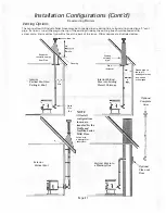
Profile 30 Insert Installation Configuration
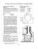
Masonry and Zero Clearance
Fireplaces
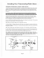
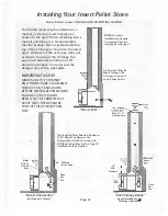
The model Profile 30-insert is approved for installation into a
solid fuel burning fireplace, either a masonry fireplace or an
approved factory-built (zero clearance) fireplace. This stove
must be connected to 3"f75mm or 4"/10 0mm pipe, using a
listed solid fuel, single wall, flex or rigid pipe (24 gage stainless
steel) as a liner is recommended.
Dimensions Into a Fireplace
Height
20 1/8'' / 512 mm
Width
24 3/8" / 620 mm
Depth
13 1/2" / 343 mm
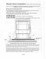
CAUTION: The fireplace in which the Profile 30-
lnsert is to be installed must be thoroughly
cleaned if it has been used to bum wood or syn
thetic logs. Have the chimney and all inside sur
faces of the fireplace brushed and vacuumed so
that no soot, embers, or loose combustion depos
its can be drawn into the heat circulation blower
and blown into the living area. If any portion of the
chimney system shows signs of structural or me
chanical weaknesses, such as: cracks, leaky
joints, corroded or warped surfaces, the faulty por
tion must be repaired or replace prior to installing
this appliance.
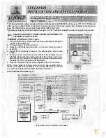
IMPORTANT: When installation the Profile 30-
insert into a factory built fireplace, the firebox must
accept the insert without modification other than
removing bolted or screwed together pieces such
as smoke shelf/deflectors, ash lips, screen or door
tracks and damper assemblies, that must be rein
stalled to restore the fireplace to its original oper
ating condition if the insert is removed and not re
place. The removal of any part ITJUSt no� alter the
integrity of the outer shell of the� pre-engineered
fireplace cabinet in any way.
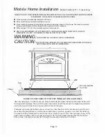
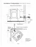
Floor Protection
The area directly in front of the insert must be protected
by a n oncombustible material or a fireplace hearth or
hearth extension as follows:
Combustible floor must be protected by non
combustible material in Canada and 10 millimeter
(3/8 inches) mil/board or equivalent non
combustible in U.S. extending beneath the heater
and to the front and sides a indicated or to the
nearest permitted combustible material.
The protected area must extend 6" to the front of the
face of the stove and 6" beyond both sides.
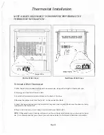
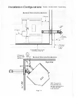
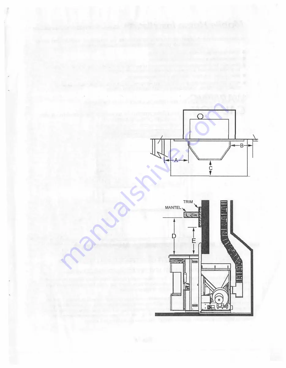
Minimum Clearances to
Combustibles
A - Insert to side wall
B - Insert to side trim
C - Hearth extension
D - Insert to mantel
E - Insert to top trim
SIDE WALL
HEARTH OR
inches/millimeters
6" 1153mm
1" 126mm
6" /153 mm
18"
1458mm
1" 1 26mm
Top View
FLOOR PROTECTION
Side View
Page 12
TRIM