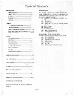

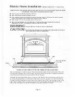
Venting Requirements
All Clearances and Instructions Listed By Vent Manufacturer Must Be Followed.
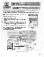
IT IS RECOMMENDED THAT ONLY AN AUTHORIZED DEALER INSTALL YOUR PELLET STOVE. THE
FOLLOWING INSTALLATION REQUIREMENTS MUST BE FOLLOWED
TO
ENSURE CONFORMITY
WITH BOTH THE SAFETY LISTING
OF
THE APPLIANCE AND LOCAL BUILDING CODES.
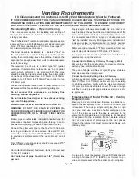
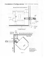
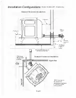
Freestanding Models - Pipe and Venting
There are several options for installing and venting of
these pellet appliances. Refer to clearances before in
stalling your stove.
The Whitfield and Tradition brand pellet appliances are
approved for use with the following vent sizes; Approved
Sizes: 3"/75mm (standard) or 4"/100mm. See page 17 -
for determining correct size vent.
The most desirable installation is to install a "Tee" on
the back of the stove and installing pipe up through the
ceiling, then terminating above the roofline. Position the
appliance far enough away from walls to allow adequate
room for servicing.
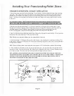
The required type of pipe is a listed type "PL" (pellet
vent pipe. It is sometimes referred to as "L-Vent pellet
vent"), which conforms to UL standard 641. The pipe
should be attached (and sealed) to the flue outlet collar
on the back of the stove. Use a 3"/75mm to 4"/100mm
adapter or a 3"/75mm to 4"/100mm Tee in order to run
4"/100mm pipe.
Choose the appliance location with the least amount of in
terference with the house framing, plumbing, wiring, etc.
Do not connect this appliance to a chimney flue
servicing another appliance.
Do not install a flue damper in the exhaust venting
system of this appliance.
Maintain clearances in accordance with NFPA 211.
WARNING: DO NOT USE CLASS B VENTING IN
TENDED FOR GAS APPLIANCES AS A CHIMNEY OR
CONNECTOR PIPE ON A PELLET FIRED APPLI
ANCE.
Follow pipe manufacturers installation '-i�tructions for
precautions required for passing pipe through a com
bustible wall or ceiling (i.e. use an approved thimble).
Connect the pellet vent pipe or the "Tee" to the flue col
lar using a minimum of three screws. Use an RTV sili
cone with a rating of at least 570
°
F (969
°
C), or lnteram
to provide a complete seal at the flue collar and on all
joints.
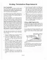
Total Offsets in venting system should not exceed 270
°
total in direction change.
Horizontal Run Allowed: Maximum total is not to exceed
10 feet (3.1 meters).
Horizontal run of pipe should have 1/4" (7 mm) rise
per foot.
Ninety-degree elbows accumulate fly ash and soot
which reduces the exhaust flow and performance of the
stove. Horizontal runs of pipe will collect fly ash as well.
It is recommended that a single or double clean-out
"tee" be installed at every 90-degree turn. Installation of
a clean-out tee is recommended to permit periodic
cleaning of both the horizontal and vertical runs of pipe.
Pellet vent pipe requires 3"/75mm clearance from out
side of pipe (all diameters: 3"/75mm & 4"/100mm).
A support bracket must be installed every 4'/1.2m of
pellet vent pipe on the exterior.
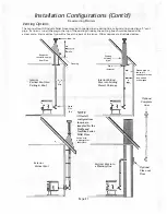
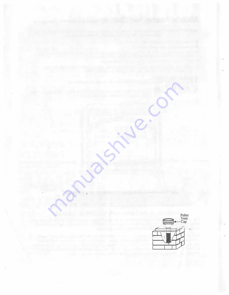
Connection to Masonry Chimney Through a Wall
Be sure to verify the construction of a masonry chimney,
as many have combustible framing.
The use of single wall flex or rigid 24-gage stainless
steel pipe as a liner is approved.
Connection to an Existing Class A Chimney
A chimney adapter can be used to make the connection
from 3"/75mm or 4"/100mm pellet vent pipe to existing
UL chimney system. Verify with the pipe manufacturer
that your pipe brands will interconnect. The use of single
wall flex or rigid pipe (24 gage stainless steel) as a liner
is approved.
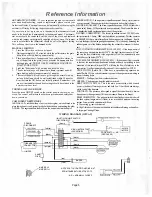
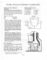
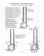
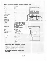
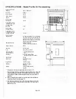
Fireplace Insert Model Profile 30 - Venting
Requirements
Masonry and zero clearance fireplace installations re
quire a full liner system. The 3"/75mm or 4"/100mm pipe
is required. When using single wall pipe, flex or rigid
liner, you must use a section of pellet vent pipe on the
top of the chimney where the pipe is exposed to the
elements. Single wall, flex, or rigid liner is not designed
for exposure to the elements. Do not insulate around
liner or use a seal off plate where the liner passes
through the damper (Air must communicate freely, with
chimney area).
I' Adjustable
Section
Pellet
Vent ----=�r'--�
3" or 4" -+--..-.
Stainless
Flex
-·----
Chase
Cover
All pipe joints must be sealed. Use an RTV silicone with
a rating of at least 570
°
F (969
°
C), or lnteram to pro
vide a complete seal at the flue collar and on all joints.
Page 15


