background image

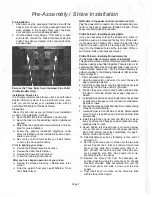
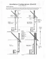
Venting Termination Requirements 

Vent Termination 

Do not terminate  vent in an enclosed or semi-enclosed 

area such as: carports, garage, attic, crawl space, under 

a deck, porch,  narrow walkway,  closely fenced area,  or 

any location that  can build up a concentration of fumes 

such as a stairwell, covered breezeway etc. 

Vent  surfaces  can  get  hot  enough  to  cause  burns  if 

touched. Adults should supervise children when they are 

in the area of a hot stove.  Non-combustible shielding or 

guards may be required. 

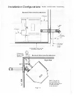
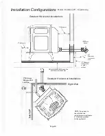
Direct-Vent  Installations: 

On  all  direct-vent  installa­

tions  (short,  horizontal  runs  with no  vertical pipe);  care 

should be taken when choosing a location for terminat­

ing  the vent.  It is not recommended to  directly vent  the 

exhaust  on  the  prevailing  wind  side  of  the house.  It  is 

recommended that when an appliance is vented directly 

through a wall,  a minimum of 8'  (2 ½ meters) of vertical 

pipe  should  be  installed  to  create  some  natural  draft. 

This will prevent the possibility of smoke or odor enter­

ing  the  dwelling  during  appliance  shutdown  or  loss  of 

power.  It will also help to keep exhaust from causing a 

nuisance  or  hazard  and  exposing  people  or  shrubs  to 

high temperatures. In any case,  the safest and preferred 

venting method is to extend the vent through the roof. 

Termination  Cap: 

The termination of the outside chim­

ney  of  the  pellet  stove  shall  be  located  in  accordance 

with the following: 

A. Higher than 3'/915mm above any forced air inlet (air

conditioner, etc.) located within 10'/3049mm.

B. Not  less  than  4'/1220mm  below,  4'/1220mm  hori­

zontally from or 1 '/305mm above any gravity air inlet

(door, wind<;>w, etc.) which flue gases could re-enter

the dwelling. 

_ _ 

.

C. Not less than 2'/610mm from combusfible materials

such  as  an  adjacent  buildings,  fences,  protruding

parts  of  the  structure,  roof  overhang,  plants  and

shrubs,  etc.  and  not  less  than  7'/2134mm  above

grade when located adjacent to the public sidewalks

(access).  The  final  termination of  the  exhaust  sys­

tem  must  be configured  so  that  flue  gases do  not

jeopardize the safety of people passing by, overheat

combustible  portions  of  nearby  structures  or  enter

the dwelling.

D. Not less than  3'/915mm below  an  eave  (maximum

overhang  of  3'/915mm)  or  any  construction  that

projects  more  than  2"/51 mm from  the plane  of  the

wall.

E. The  distance  from  the  bottom  of  termination  and

grade  - 12"/305mm  minimum.  This  is  conditional

upon  plants  and  nature  of  grade  surface:  The  ex­

haust  gases  are  not  hot  enough  to  ignite  grass,

plants and  shrubs located  in the  vicinity  of  the  ter­

mination  although  they  should  be  a  minimum  of

3'/915mm away. The grade surface must not  be  a

lawn.

F. Since sparks may escape from the exhaust pipe of

any stove,  always use caution when positioning the

vent  pipe  refer  to  pipe  manufacturer's  instructions

when  installing  and  terminating  the  exhaust.)  The

vent  pipe  should  be  horizontal  and  never  run  the

pipe  in  a  downward  direction  (recommend  a  ¼"/

7mm rise per foot horizontal).

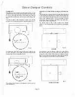
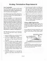
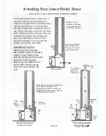
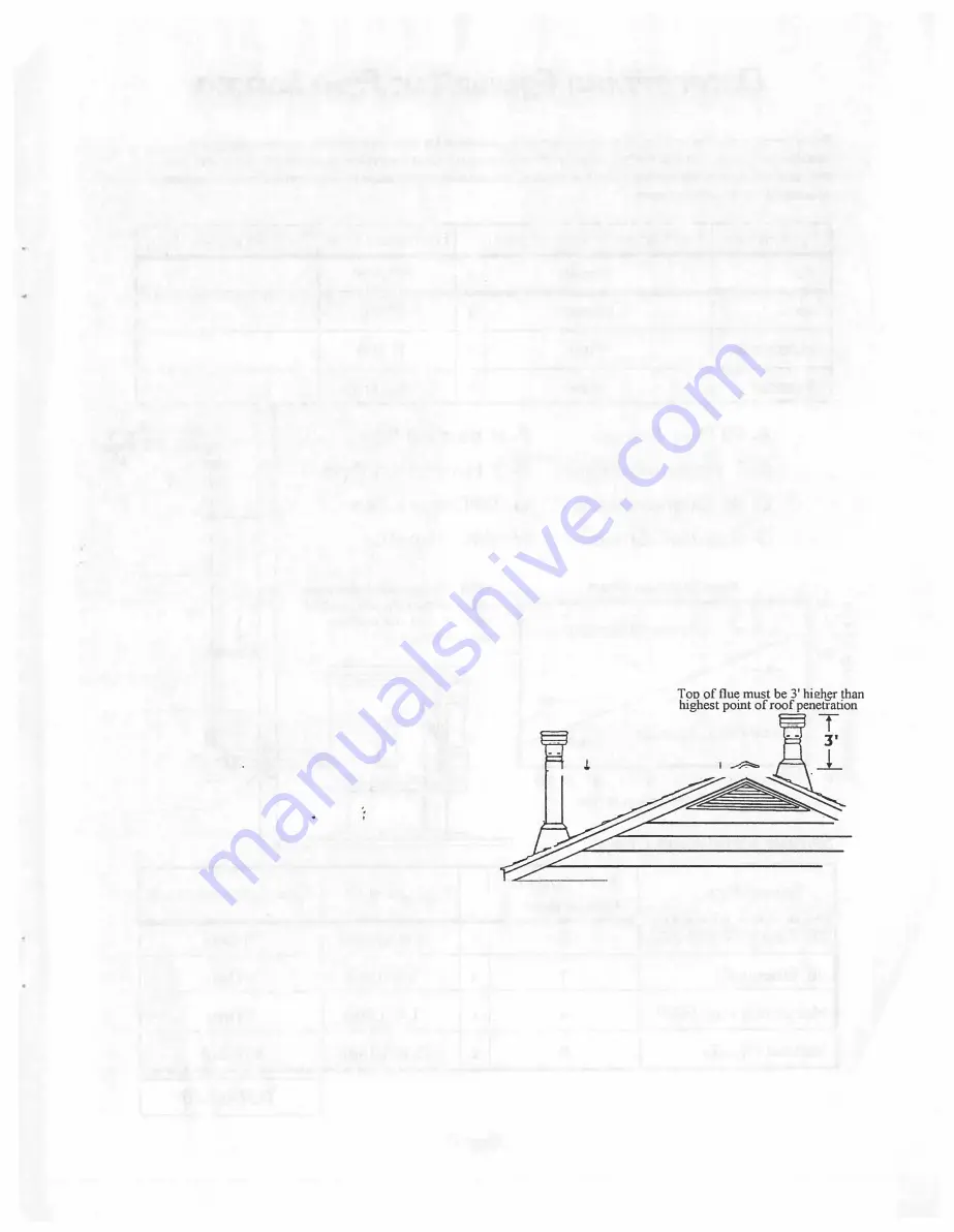
Chimney Height Requirements 

The chimney must extend 3'/915mm above the level of roof 

penetration  and  a  minimum  of  2'/610mm  higher  than  any 

roof surface within 10'/3049mm feet (see below).  Check with 

your  local  building  officials  for  additional  requirements  for 

your area. 

Due to prevailing winds, local terrain, adjacent tall trees, a hill 

or  ravine  near  the  home,  or  adjacent  structures,  a 

_

special 

chimney  cap may be required to ensure optimum perform­

ance. 

Top of flue must be 2' 

, higher than any part of 

2  roof·within  10' horizontal 

l+-

-'-

--10'---�-.:?T"� 

To pass inspection in nearly any jurisdiction, the chim­

ney must meet both safety and exhaust flow require­

ments. The  (3' by) 2' by 1 O' rule applies to both ma­

sonry and factory built chimneys. 

Page 16 

Summary of Contents for Traditions Freestanding P11

Page 1: ...allation restrictions and inspection requirements in your area Do not use class B venting intended for gas appliances as a chimney or connector pipe on a pellet fired appliance Do not connect this appliance to a chimney flue connected to another appliance Warnock Hersey Burning any kind of fuel consumes oxygen If outside air is not ducted to the appliance ensure that there is an adequate source of...

Page 2: ...ve from the wall outlet 3 Locate the thermostat terminal block on the back of the stove see il lustration 4 Loosen the two terminal screws on the terminal block and remove jumper 5 Connect the two wires from your thermostat to the terminals one per terminal Ensure that the purple wires from the harness remain con nected to the terminal block and tighten the terminal screws Make sure the wires are ...

Page 3: ...Plate SAVE THESE INSTRUCTIONS 23 24 24 24 25 25 25 25 26 28 29 32 33 35 36 37 38 39 41 PRODUCT IS SUBJECT TO CHANGE WITHOUT NOTICE Page 2 PACKAGING LIST The assembled pellet stove models P11 Traditions Profile 20 freestanding Profile 30 freestanding and Profile 30 insert are packaged with an accessory pack age which contains the following One Installation and operation instructions man ual One Pow...

Page 4: ...lowers motors and electronic controls and is not recommended Typical approved operation would include running at the low to mid range setting with occasional running on the maximum setting during the coldest periods of the winter The blower speed control should be turned to high when operating the stove on the high heat setting Liquid Flammables Gasoline or other flammable liquids must NEVER be us...

Page 5: ...el for model Pl 1 and in the hopper for the Profile models Please read the label carefully It contains important information about installation and operation of your Lennox Hearth Prodl cts Pellet Stove This Owner s Manual is provided to you to supplement rather than replace or update the information contained on the safety label Note that your STOVE S serial number is located on the safety label ...

Page 6: ...0 CFM cubic feet perminute 8amp 2178rpm revolutions per minute The blowers function is to transfer the heat from the applianceto heat the room air BLOWER COMBUSTION The blower specifications are 95 CFM cubic feet per minute 1 0 amp 2880 1pm revolutions per minute This fan operates at 2800 RPM It has a radial impeller to deliver more air to the firepot It pulls airinto the firepot bycreating a nega...

Page 7: ...ormed in the burning process Clinkering is a function of the fuel not the stove but adversely affects the performance of the stove by blocking off the air passages in the grate Even P F 1 approved pel let fuel may tend to clinker A clinker can be removed from the burn grate and placed in the ash pan with the use of the grate scraper ash pan tool furnished with your stove See Routine Maintenance fo...

Page 8: ... 2 leveling bolts 1 4 20 x 3 long into the threaded holes at the rear base of the in sert Adjust bolts until appliance is level Profile 30 Insert Installing Shroud Assembly To be done after venting system is installed This appliance comes with a set of metal panels that seal the fireplace opening when fitted together There is also a trim assembly that frames the shroud assembly to give it an at tr...

Page 9: ...ns Pellet Stove 1 A 24 thermostat is inclu cj_ with iyour stove accessories along with a length of thermostat wire 1 2 Unplug your stove from the wall outlet 3 Locate the thermostat connection block on the back of the stove 4 Remove thejumper wire from the acks on the connection block 5 Insert the two wires from your thermostat into thejacks one perjack Make sure the wires are firmly connected to ...

Page 10: ... damper one notch at a time until proper combustion is attained the flame should become yellow and begin to dance If the flame is short at the higher bum rates or if the pellets are burning up in the grate before new pellets are fed into the fire push the damper in one notch and monitor the flame Continue the process of moving the damper one notch at a time and evaluating the flame until proper fl...

Page 11: ...standing and Profile 30 In sert The damper rod is located behind the right hand side panel of the Profile 20 freestanding and behind the left hand side panel of the Profile 30 freestanding and on the left surround panel of the Profile 30 Insert It is very important to setup your damper prior to burning your Profile series pellet stove as it is likely to shift during shipment The damper plate on th...

Page 12: ...and extend 6 to the front of the face of the door opening and O be yond both sides and back of the stove body Hearth Pad 1 5n 5n Page 11 Clearances Model Traditions P11 Freestanding Standard Residential or Manufactured Mobile Home Installation These appliances require the following minimum clear ances to combustibles Stove Clearances to Combustibles inches inch millimeter Back Wall 2 51mm Side Wal...

Page 13: ...NT When installation the Profile 30 insert into a factory built fireplace the firebox must accept the insert without modification other than removing bolted or screwed together pieces such as smoke shelf deflectors ash lips screen or door tracks and damper assemblies that must be rein stalled to restore the fireplace to its original oper ating condition if the insert is removed and not re place Th...

Page 14: ...Y OF THE MANUFACTURED HOME FLOOR WALL AND CEILING ROOF MUST BE MAINTAINED is t Floor t if I J _ r _jV Bo t J w MOBILE HOME EXHAUST VENT PIPE INSTALLATION GUIDELINES No Flo n combustible or Pad Use only listed type L pellet vent pipe Pipe should extend at least 3 feet above the part of the roof through which it passes The top of the pipe should be at least 2 feet above the highest required ele vati...

Page 15: ...RUCTURAL INTEGRITY OF THE MANUFACTURED HOME FLOOR WALL AND CEILING ROOF MUST BE MAINTAINED Floor Non combustible Floor Pad MOBILE HOME EXHAUST VENT PIPE INSTALLAT ION GUIDELINES Use only listed type L pellet vent pipe Pipe should extend at least 3 feet above the part of the roof through which it passes The top of the pipe should be at least 2 feet above the highest required ele vation of any part ...

Page 16: ...69 C or lnteram to provide a complete seal at the flue collar and on all joints Total Offsets in venting system should not exceed 270 total in direction change Horizontal Run Allowed Maximum total is not to exceed 10 feet 3 1 meters Horizontal run of pipe should have 1 4 7 mm rise per foot Ninety degree elbows accumulate fly ash and soot which reduces the exhaust flow and performance of the stove ...

Page 17: ...buildings fences protruding parts of the structure roof overhang plants and shrubs etc and not less than 7 2134mm above grade when located adjacent to the public sidewalks access The final termination of the exhaust sys tem must be configured so that flue gases do not jeopardize the safety of people passing by overheat combustible portions of nearby structures or enter the dwelling D Not less than...

Page 18: ...8 Vertical Pipe F 2 Horizontal Pipe G 90 Degree Tee H Wall Thimble 4i 30 rc NOTE All equivalent pipe styles shown to the right are standard for the Profile and Tradition Series Pellet Stove QJ I I I I I I I I I I u __ r 4 INCH DIAMETER ONLY 1 I I I I I I I I 20 1 l J cn I l I I I I C 1 1 I I I I I Q I I I I I I I I I J I t I I I I I I QJ I l I I I I I I a C 10 r r r 7 r 1 I I I I I I I I 3 o R 4 1...

Page 19: ...ipe will go through the wall thimble Do not position the back of the stove closer than 1 25mm from the wall Note Greater back clearance will improve the serviceability of the stove 4 Install listed type L 45 degree elbow with rodent screen or cap optional on outside end of pipe The rodent screen should be no less than 1 2 13mm mesh and may clog with soot and ash if left unattended during the burn ...

Page 20: ...uter wall I II I 12 Minimum from ground or other 3 Minimum Between Wall and Pipe 11 J _ NON COMBUSTIBLE Hearth Pad 3 8 Minimum Thickness surfaces K I 11 I 1 I 11 J f t I 11 I I I Standard Horizontal Installations I I Page 19 Right Wall NOTE Ifyou vent to the Furthest Wall the vent pipe must maintain a 3 clearance parallel to the other wall ...

Page 21: ...12 Minimum from outer wall ___ 12 Minimum from ground or other surfaces 3 Minimum Between Wall and Pipe r NON COMBUSTIBLE Hearth Pad 3 8 Minimum Thickness Standard Horizontal Installations Page 20 Right Wall NOTE If you vent to the left wall the vent pipe must maintain a 3 clearance parallel to the right wall ...

Page 22: ...r options are illustrated below Keep attic Insulation away from Pipe Interior Vertical Vent thru Ceiling Roof Exterior Vertical Vent Existing chimney m 1 pipe Flashing 3 Min t w l __ 1f 4 Clean Out Tee NOTE All Install configurations shown are standard for the Profile and Tradition Series Pellet Stove Shown with Advantage Plus Pellet Stove Pipe 1 r increaser Interior Vertical Vent into Existing Cl...

Page 23: ...URE THE CHIMNEY AND FIREBOX ARE CLEAN AND FREE OF SOOT AND ASHES BEFORE INSTALLATION BEGINS FAILURE TO DO SO MAY RESULT IN THE TRANSFER OF SOOT INTO THE ROOM BY WAY OF THE CONVECTION FAN Direct Vent The Vent Pipe Must Extend A Minimum Of 18 Above The Damper The Chimney Must Not Be Corroded Or Metal Plate To Provide Seal Direct Connection Not Allowed In Canada Q ed In Any Way For This Type Of Insta...

Page 24: ... H l _ Fil JII ____ Off 11 I 1 11 _ I pressing the Calibration button on the front of the control panel located behind the swing down door Once the calibra tion button is pressed the Auger led will illuminate Once in the Fuel Trim Mode the HEAT button is used to select the adjustment of the pellet feed rate NOTE It is recommended that the damper be used to fine tune your stove to your particular f...

Page 25: ...e tum the stove OFF and then back ON The auger tube should now be primed and the stove should deliver enough fuel for proper ignition It may be necessary to follow these procedures in the event that the hopper runs completely out of fuel Manual Operation Pressing the stove on off switch initiates the start up cycle The green on off light near the top of the control will light up to indicate the on...

Page 26: ...rning Burn times can vary plus or minus 2 hours depending on the type of pellets burned When utilizing the thermostat capability the burn time can be extended dramatically depending on ther mostat setting Note It is normal for some ash to build up on the inner glass surface at the lower burn settings AUTOMATIC SAFETY FEATURES Power Outage During a power outage the stove will shut down safely The s...

Page 27: ...e ash pan fig A Creosote removal When wood is burned slowly it produces tar and other organic vapors which combine with expelled mois ture to form creosote The creosote vapors condense in the relatively cool chimney flue of a slow burning fire As a result creosote residue accumulates on the flue lining When ignited this creosote makes an extremely hot fire The chimney connector and chimney should ...

Page 28: ...or Seal Periodically insert a small piece of cardboard a business card between the window trim and the window Slide the card back forth a few times to clear any dust or fibers from the window wash gap Open the door and repeat from the other side of the glass l Traditions Window Wash Profile 20 and 30 Window Wash Page 27 paper in several different locations and pull It is nor mal to feel only a sli...

Page 29: ...The rear stove compartment should be cleaned periodi cally a minimum of once a year DISCONNECT ELEC TRICAL CORD PRIOR TO CLEANING STOVE Any household dust pet hair or sawdust should be vacu umed or wiped out of the rear compartment of the stove Freestanding or Fireplace Insert model The electrical components should be wiped clean HEAT EXCHANGER TUBES TRADITIONS ONLY CLEAN HEAT EXCHANGER TUBES AFTE...

Page 30: ...6 to the front of the face of the stove and 6 beyond both sides and back of appliance Fastfire Self Igniter Wall Thennostat wire included 55 lbs 15 37 hours 5 amp 250 volt 3AG 13 000 32 000 BTU hr 75 81 0 9 grams hr varies w size and type of fuel EPA exempt 215 lbs 150 CFM 8 amps 2175 rpm 1 RPM 4 amps 95 CFM 1 0arrips 288 rpm Nickei or Geld Trim Kits Log Set Dimensions shown are approximations onl...

Page 31: ...of the stove and 6 beyond both sides and back of appliance Fastfire Self Igniter Wall Thermostat wire included 80Ibs 18 48 hours 5 amp 250 volt 3AG 14 000 39 000 BTU hr 81 0 9 gr hr varies w size and type of fuel EPA certified 270 lbs 150 CFM 8 amps 2175 rpm 1 RPM 4 amps 95 CFM 1 0a ps 2880 rp_m _ Nickel or Gold Trim Kits Log Set Dimensions shown are approximations only Square footage heating capa...

Page 32: ... Fastfire Self Igniter Wall Thermostat wire included 50 lbs 12 40 hours 5 amp 25 volt 3AG 9 900 32 000 BTU hr 85 0 9 gram hr varies w size and type of fuel EPA certified 360 lbs 150 CFM 8 amps 2175 rpm 1 RPM 4 amps 95 CFM 1 0arpps 2880rpm NicRel or Q gltl Trim Kits Log Set Dimensions shown are approximations only Square footage heating capacities are approximations only They will varydepending upo...

Page 33: ... 1 8 12 7 16 Non combustible floor protection must fully cover the area beneath the appliance and extend 6 to the front of the face of the stove and 6 beyond both sides of appliance Fastfire SelfIgniter Wall Thermostat wire included 50Ibs 10 45 hours 5 amp 250 volt 3AG 14 000 39 000 BTU hr 81 0 9 gram hr varies w size and type of fuel EPA certified __ lb 150 CFM 8 amps 2175 rpm 1 RPM 4 amps 95 CFM...

Page 34: ...cessary Check that the damper has been opened enough for the amount of fuel feed Check that the heat exchange tubes are not coated with ash Clean internal exhaust ducts Check gasket seal around the door Use a thin strip of paper 1 in wide Open the door and close it on the paper strip A slight friction should be felt when the paper strip is pulled Repeat this process at vari ous locations around th...

Page 35: ...d down low then the fan should be turned up higher If this problem persists particularly at lower burn rates then the high limit snap switch should be replaced by your certified Hearth Trends dealer Adjust the damper to reduce com bustion air flow Refill hopper Check to be sure that there is no blockage in the pressure tap or hose Have your certified Hearth trends dealer diagnose the problem and c...

Page 36: ...king Excessive sun light may be s ining directly into firebox om window The igniter element may have failed Page 35 Check that the stove is plugged in to the wall outlet Check to see if your circuit breaker has tripped Check the wire connections on the high limit snap switch and Control board Turn down the convection fan or turn off stove before cleaning to prevent dispersion of ash and soot into ...

Page 37: ... warranty have been complied with the Manufacturer s sole duty and liability under this warranty shall be limited to the Manufacturer s replacement or repair at Manufacturer s option of the defective stove or part The purchaser shall assume all costs of shipping to and from the Manufacturer and shall be responsible for all losses dur ing shipment if the stove ls not defective If a stove is found t...

Page 38: ...30 Insert Surround Shroud Panels and Trim O I Panel and Trim Sizes Large 36 91 4 cm height 48 121 9 cm width Medium 32 81 3 cm height 44 111 75 cm width Small 28 72 4 cm height 40 103 5 cm width 1 e Page 37 I 0 0 11 1 I 1 lj I I I lj I ...

Page 39: ... Medium IN 11750003 Door Handle Assembly Kit 14758100 Shroud Large IN 16055150 Control Board 14750201 Trim Large Shroud Gold IN 19050196 Photoeye Assembly o f l 14750101 Trim Medium Shroud Gold IN 20959999 Door Glass 19350008 Trim Small Shroud Gold IN 61057208 Glass Gasket 4 15051547 Gasket Door 3 4 Rope 8 ft Profile 20 Freestanding 11750011 Brick Clips 2 clips 14650001 Firebrick Set 20950100 Rear...

Page 40: ...53MM D O LL IUU II a 2 51 MM 9 229MM CORDANCE WITH OREGON ADMINISTRATIVE RULES 814 23 900 H _ 1 2 51MM 2 51MM 1 3MM 8 153MM THROUGH814 23 909 MAX DEPTH OFALCOVE E FLUETOWALL F 18 468MM t8 458MM WA 3 ll7UM OPERATE ONLY WITHFIREBRICK IN PLACE WARNING OPERATE __ _ _ _____ __ _ _ ___ _____________ _____ _ wuvc uw _ our ul FRONT REAR SIOETOFLOOR 6 153MU 6 153MM ONLY WITH VIEWING DOOR CLOSED INSPECT FLU...

Page 41: ...EALERFORMOREINFORMATION INPUTRATING RANGE 1 5TO3 8 LBS HOUR NOMINAL ELECTRICAL RATING 60 HZ 115 V LESSTHAN 10AMP DO NOT REMOVETHISLABEL WH MINIMUMCLEARANCES TO COMBUSTIBLE MATERIALS MOBILE HOMEOA RESIDENTIAL INSTALLATION FREESTANDING STOVE HORIZONTAL FLUE INTEAIOA INSTALLATION OIRECTLYTHFIOUGHWALL VERTICAL FLUE INSTALLATION INSTALLATION SIDEWALLTO UNIT A no2MM 4 102MM BACKWALL TO UNIT B 1 126MM 9 ...

Page 42: ...UR MANUALAND DEALER FOR MORE INFORMATION DO NOTREMOVETHIS LABEL WH 1 tN g __9 QCOM8UST TE FREm1 0VE t 81LEHOUEORRESIOENTW lNSTAU ATION HOAIZONW FLUE DIAECTI YTHAOUGHWA U INTtRlORto lfflCAl flUf 111J WAU IO 1 1153 1 f113MM IACKW W TDUMlt I 1 ne r1221 DOflBfOlllff C 1 21 U OWflOMlllilOl EI D 1 11a 11a DIPTiftfAUXM 11 c fUETOWAll r s m 8 0tW4LL AOJACENTWAU R 1ITT ti INlfRTOADUlt l4N Ii I SID WAU l 11...

Page 43: ...lENNOXe HEARTH PRODUCTS 4325 Artesia Avenue Fullerton CA 92833 ...

Page 44: ...f ...

Reviews: