
i
/
�����������$����
s�·
srancl�
·
.Whitfield
�!arid
-Tradi
.
-
'
n,:
t
"
-
-
--:;:��:
�
�
S"'=
�;,-,=-
...
-����i ..
i-
-
--
���,r_c>!!!,�2.:�,;.ft�t�
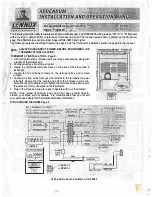
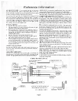
The following correction affects Installation and Operation Manual, part# 20922000 with a revision "IR", "A" or Ms•. Manuals
with a revision
C
(March 2001) or later have this correction. Note: The manual revision date is printed on the front cover
page. The affected stove serial number range is #146-03813 and higher
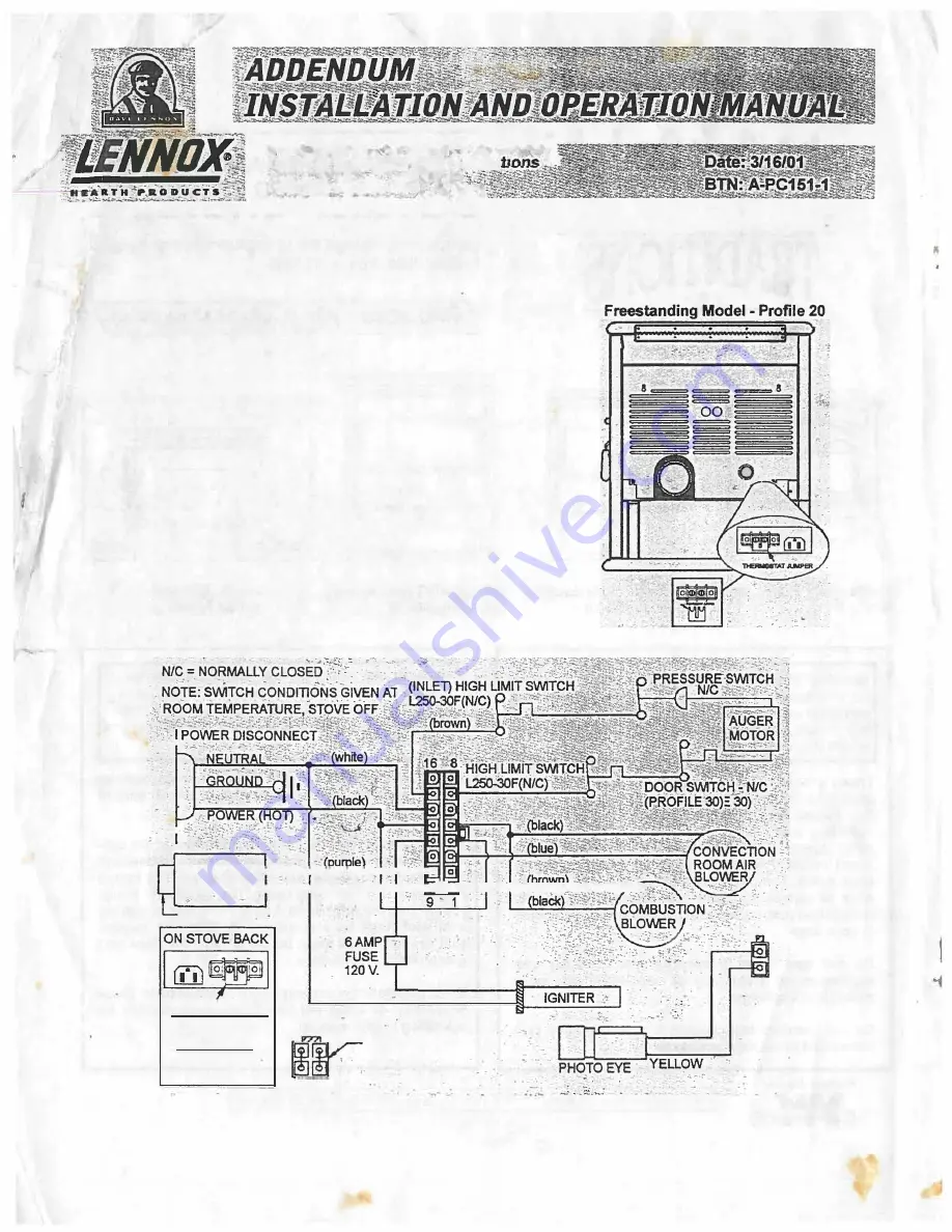
The following replaces the Wiring Diagram on page 5 and the Thennostat Installation section on page 8 in the manual:
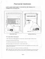
NOTE: ALWAYS DISCONNECT POWER BEFORE PERFORMING THE
�1
THERMOSTAT INSTALLATION.
'
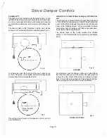
THERMOSTAT INSTALLATION - Page 8:
1 . A 24volt thermostat is included with your stove accessories, along with
a length of thermostat wire.
2.
Unplug your stove from the wall outlet.
3.
Locate the thermostat terminal block on the back of the stove (see il
lustration).
4. Loosen the two terminal screws on the terminal block and remove
jumper.
5.
Connect the two wires from your thermostat to the terminals (one per
terminal). Ensure that the purple wires from the harness remain con
nected to the terminal block and tighten the terminal screws. Make sure
the wires are firmly connected to the thermostat.
6.
Plug in the stove and you are ready to operate with your thermostat!
NOTE: If the jumper is missing, and you do not have a thermostat in
stalled, your stove will not operate. It is recommended that you consult
your authorized dealer for thermostat installation information.
STOVE WIRING DIAGRAM-Page 5
'
THERMOSTATi-----.......::-...:......a.....,._,.....__..,
.. :�
CONNECTORt---+-�(p-u���le�)..,.._-,.....---1ot1e+--+___;;�==.,...,;...;.;;,..��
JUMPER
lliERMOSTAT JUMPER
aw
�
.
(red)
(red)
2
I
.
.
JUMPER 1-3
-
JUMPER 2-4
.
4 3
. -- ,
-
- -
-
.. -
.··t,
- , ... .: .. ..
--
-
..
.
4325 Artesia Avenue Fullerton, CA 92833
,.-
,:,
.. · •·
YELLOW
,,
.,
I