Page 37
XC21 SERIES
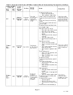
Table 10. Compressor Alert Codes (A175 Main Control LEDs and Communicating Thermostat User Interface)
Outdoor A175 Main
Control LEDs
icomfort
Touch
t
Thermostat
Display
Condition
Possible
Cause(s)
Solution
Clearing Status
DS15
Yellow
DS13
Red
OFF
ON
Moderate/
Critical Alert
Code 400
Compressor
Internal
Overload Trip
Thermostat
demand signal Y1
is present, but
compressor not
running
1
Compressor protector is open.
S
Check for high head pressure
S
Check compressor supply voltage
2
Outdoor unit power disconnect is open.
3
Compressor circuit breaker or fuse(s) is
open.
4
Broken wire or connector is not making
contact.
5
Low or high pressure switch open if pres-
ent in the system.
6
Compressor contactor has failed to close.
Clears the error after
current is sensed in the
run and start winding for
two seconds, service
removed or power reset.
1 Flashes
then
Pause
OFF
Critical Alert
Code 401
Long run time.
Compressor is
running extremely
long run cycles.
1
Low refrigerant charge.
2
Evaporator blower is not running.
S
Check blower relay coil and contacts
S
Check blower motor capacitor
S
Check blower motor for failure or
blockage
S
Check evaporator blower wiring and
connectors
S
Check indoor blower control
S
Check thermostat wiring for open cir-
cuit
3
Evaporator coil is frozen.
S
Check for low suction pressure
S
Check for excessively low thermostat
setting
S
Check evaporator airflow (coil block-
ages or return air filter)
S
Check ductwork or registers for block-
age.
4
Faulty metering device.
S
Check TXV bulb installation (size,
location and contact)
S
Check if TXV/fixed orifice is stuck
closed or defective
5
Condenser coil is dirty
.
6
Liquid line restriction (filter drier blocked if
present)
.
7
Thermostat is malfunctioning
.
S
Check thermostat sub−base or wiring
for short circuit
S
Check thermostat installation (loca-
tion and level)
Clears the error after 30
consecutive normal run
cycles, or after power
reset.
2 Flashes
then
Pause
OFF
Critical Alert
Code 402
System
Pressure Trip
Indicates the
compressor
protector is open
or missing supply
power to the
compressor.
1
High head pressure.
S
Check high pressure switch if present
in system
S
Check if system is overcharged with
refrigerant
S
Check for non−condensable in system
2
Condenser coil poor air circulation (dirty,
blocked, damaged).
3
Condenser fan is not running.
S
Check fan capacitor
S
Check fan wiring and connectors
S
Check fan motor for failure or block-
age
4
Return air duct has substantial leakage.
Clears after four
consecutive normal
compressor run cycles,
or after power reset.
Summary of Contents for XC21
Page 21: ...Page 21 XC21 SERIES Figure 8 Typical XC21 Wiring ...
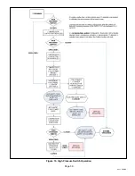
Page 39: ...Page 39 XC21 SERIES Figure 19 High Pressure Switch Operation ...
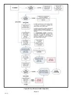
Page 40: ...Page 40 506518 01 Figure 20 Low Pressure Switch Operation ...
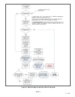
Page 41: ...Page 41 XC21 SERIES Figure 21 High Discharge Temperature Sensor Operation ...


