Page 42
506518−01
Maintenance
WARNING
Electric shock hazard. Can cause injury
or death. Before attempting to perform
any service or maintenance, turn the
electrical power to unit OFF at disconnect
switch(es). Unit may have multiple power
supplies.
DEALER
A175 MAIN CONTROL UNIT SIZE CODE
CONFIGURATION
In a communicating system, if the thermostat user
interface is indicating a unit size code error (see outdoor
unit installation instruction for error code) with the outdoor
main control, the following procedure must be followed to
set the unit size code using the A175 main control’s test
pins.
1. Remove 24 volts from control.
2. If leads are connected to the A175 main control’s
terminals
i−
and
i+
,
remove leads prior to starting
this procedure
.
DISCONNECT WIRES FROM
BOTH I+ AND I− TERMINALS
Figure 22. Terminals (i− and +−)
3. Place jumper on
FIELD TEST
pins (E33) (see page 22
for location of
FIELD TEST
pins).
4. Apply power to A175 control’s
R
terminal (See figure
4 for location of terminal).
5. Remove jumper from
FIELD TEST
pins (E33)
between 0−10 seconds, and then jumper again
between 0−10 seconds.
6. A175 main control’s DS11 and DS14 LEDs (see page
22 for location of LEDs) will start blinking the
Unit
Nominal Capacity Code
for 1 − 6 tons with interval of
three (3) seconds (see table 4 for codes).
7. Long blink on red LED (DS14) to indicate integer
tonnage and solid on green LED (DS11) to indicate 1/2
tonnage.
Example
: 2−1/2 ton is indicated by two long blinks on
the red LED
(DS14)
and solid on for the green LED
(DS11)
.
8. When the required LED capacity code (see table 1)
has displayed on the A175 main control,
remove the
jumper from FIELD TEST pins while the code is
still displaying.
9. The A175 main control will continue to display the
unit
nominal capacity code
until 24 volts is removed from
control.
10. Reconnect control wiring to A175 main control’s
i−
and
i+
terminals.
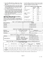
Table 11. Unit Size Code Display Sequence
Model
Size
Size
DS11
Green LED
DS14
Red LED
−024
2−TON
OFF
2 Long Flashes
−030
2.5−TON
ON
2 Long Flashes
−036
3−TON
OFF
3 Long Flashes
−042
3.5−TON
ON
3 Long Flashes
−048
4−TON
OFF
4 Long Flashes
−060
5−TON
ON
5 Long Flashes
A177 FAN MOTOR CONTROL LED CODES, JUMPER
SETTINGS AND SEQUENCE OF OPERATION
During start up, the LED will first display any error
conditions (see table 14) if present. If no errors are
detected then the LED code indicating stage operation
(see table 15) will display then a long pause. The RPM
indicator is displayed next (see tables 16. After the RPM
indicator is displayed there is a short pause and the
sequence repeats if a thermostat demand is still present.
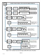
See figure 23 for LED sequence of operations. See table
15 for description of flash and pause durations.
A177 FAN MOTOR CONTROL TROUBLESHOOTING
This A177 fan motor control is used with motors which use
a Pulse Width Modulation (PWM) controller. A PWM signal
will run the fan motor at a revolutions per minute (RPM)
that corresponds to a specific PWM signal.
Verifying Jumper Settings (J2)
The unit is shipped from the factory with the default motor
RPM setting required for the specific model size. Use the
table 16 for two−stage operation to verify that jumpers are
set correctly for the specific size unit.
Verifying LED Status Codes
During start up, the fan motor control LED will
display any error conditions. If error conditions
exist then no other codes will display. If no error
conditions are present, then the stage status and
and RPM indicator are displayed.
Two−stage units
have various fan motor speed operations available (see
table 16).
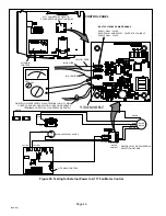
Verifying Correct DC Output Voltage (J2)
The following three methods can be used to determine
whether the fan motor is operating at the correct RPMs
based on unit size.
1. Use the information provided in table 16 to verify that
all four jumper terminals are set correctly for the
specific size unit.
Summary of Contents for XC21
Page 21: ...Page 21 XC21 SERIES Figure 8 Typical XC21 Wiring ...
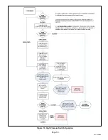
Page 39: ...Page 39 XC21 SERIES Figure 19 High Pressure Switch Operation ...
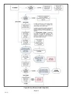
Page 40: ...Page 40 506518 01 Figure 20 Low Pressure Switch Operation ...
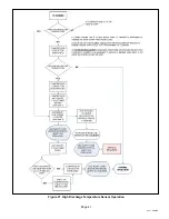
Page 41: ...Page 41 XC21 SERIES Figure 21 High Discharge Temperature Sensor Operation ...

