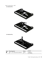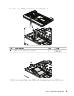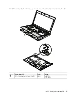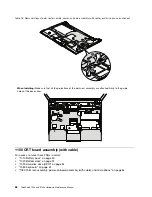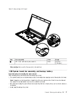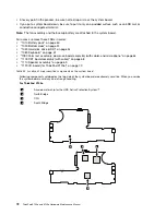
Table 11. Removal steps of DIMM (continued)
Note:
If the computer you are servicing has two DIMM slots and only one DIMM is used, the card must be installed
in SLOT-0 (
a
), but not in SLOT-1 (
b
). Some models only have one DIMM slot.
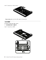
When installing:
Insert the notched end of the DIMM into the socket. Press the DIMM firmly, and pivot it until it
snaps into the place. Make sure that it is firmly fixed in the slot and does not move easily.
1050 PCI Express Mini Card for wireless LAN
For access, remove these FRUs in order:
•
“1010 Battery pack” on page 50
•
“1020 Bottom door” on page 51
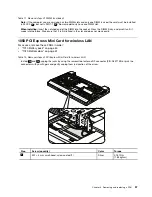
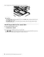
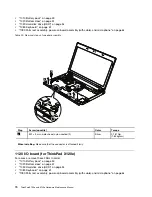
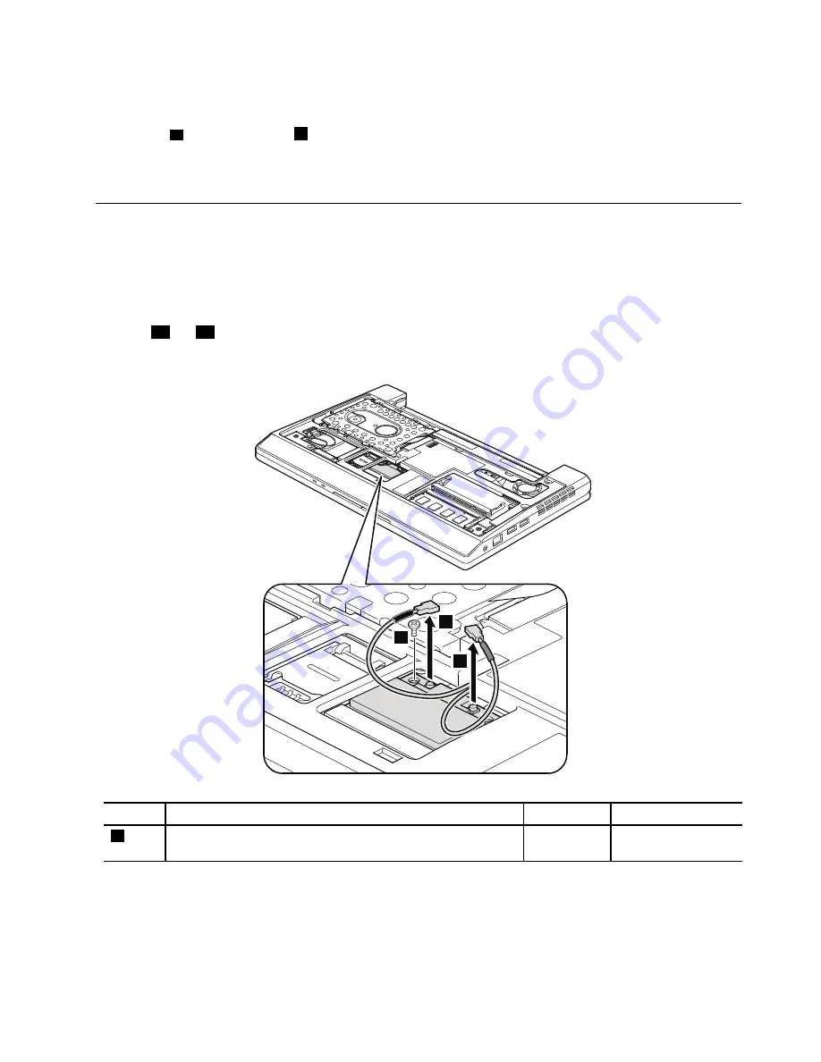
Table 12. Removal steps of PCI Express Mini Card for wireless LAN
In step
1a
and
1b
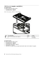
, unplug the jacks by using the removal tool antenna RF connector (P/N: 08K7159) or pick the
connectors with your fingers and gently unplug them in direction of the arrow.
1a
1b
2
Step
Screw (quantity)
Color
Torque
2
M2 × 3 mm, small-head, nylon-coated (1)
Silver
0.181 Nm
(1.85 kgfcm)
Chapter 8
.
Removing and replacing a FRU
57
Summary of Contents for 059624U
Page 1: ...ThinkPad X100e and X120e Hardware Maintenance Manual ...
Page 6: ...iv ThinkPad X100e and X120e Hardware Maintenance Manual ...
Page 18: ...12 ThinkPad X100e and X120e Hardware Maintenance Manual ...
Page 19: ...Chapter 1 Safety information 13 ...
Page 22: ...16 ThinkPad X100e and X120e Hardware Maintenance Manual ...
Page 26: ...20 ThinkPad X100e and X120e Hardware Maintenance Manual ...
Page 50: ...44 ThinkPad X100e and X120e Hardware Maintenance Manual ...
Page 54: ...48 ThinkPad X100e and X120e Hardware Maintenance Manual ...
Page 94: ...88 ThinkPad X100e and X120e Hardware Maintenance Manual ...
Page 120: ...LCD FRUs 1 4 3 2 5 7 6 114 ThinkPad X100e and X120e Hardware Maintenance Manual ...
Page 132: ...126 ThinkPad X100e and X120e Hardware Maintenance Manual ...
Page 135: ......
Page 136: ...Part Number 63Y0640_02 Printed in 1P P N 63Y0640_02 63Y0640_02 ...

