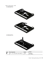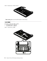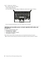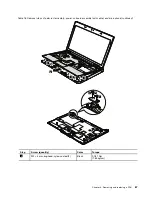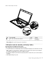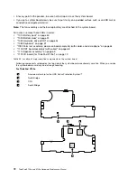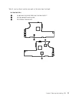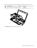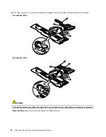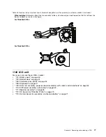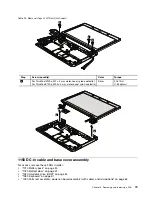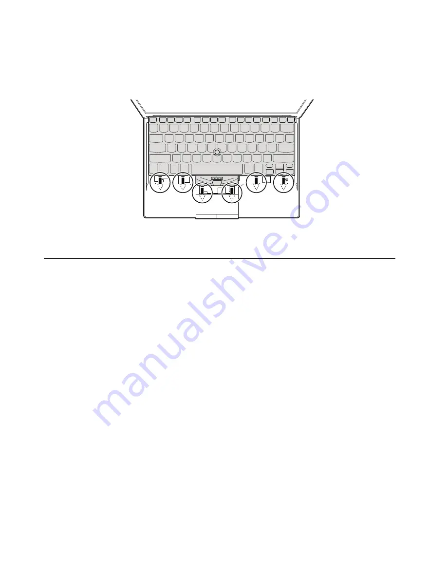
Table 17. Installation steps of keyboard
When installing the keyboard, do as follows:
1. Attach the keyboard connectors.
2. Attach the keyboard so that the front edge of the keyboard are under the frame as shown in this figure.
3. Secure the keyboard by tightening the screws from the bottom side of the computer.
1090 Palm rest assembly, power-on board assembly (with cable), and
microphone
For access, remove these FRUs in order:
•
“1010 Battery pack” on page 50
•
“1020 Bottom door” on page 51
•
“1030 Hard disk drive (HDD)” on page 54
•
“1080 Keyboard” on page 61
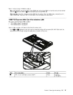
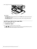
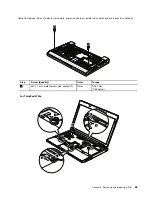
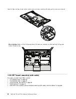
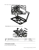
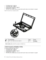
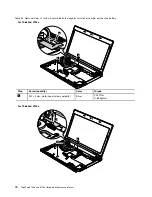
Table 18. Removal steps of palm rest assembly, power-on board assembly (with cable), and microphone
Note:
The power-on board assembly (with cable) and the microphone are attached to the palm rest assembly.
64
ThinkPad X100e and X120e Hardware Maintenance Manual
Summary of Contents for 059624U
Page 1: ...ThinkPad X100e and X120e Hardware Maintenance Manual ...
Page 6: ...iv ThinkPad X100e and X120e Hardware Maintenance Manual ...
Page 18: ...12 ThinkPad X100e and X120e Hardware Maintenance Manual ...
Page 19: ...Chapter 1 Safety information 13 ...
Page 22: ...16 ThinkPad X100e and X120e Hardware Maintenance Manual ...
Page 26: ...20 ThinkPad X100e and X120e Hardware Maintenance Manual ...
Page 50: ...44 ThinkPad X100e and X120e Hardware Maintenance Manual ...
Page 54: ...48 ThinkPad X100e and X120e Hardware Maintenance Manual ...
Page 94: ...88 ThinkPad X100e and X120e Hardware Maintenance Manual ...
Page 120: ...LCD FRUs 1 4 3 2 5 7 6 114 ThinkPad X100e and X120e Hardware Maintenance Manual ...
Page 132: ...126 ThinkPad X100e and X120e Hardware Maintenance Manual ...
Page 135: ......
Page 136: ...Part Number 63Y0640_02 Printed in 1P P N 63Y0640_02 63Y0640_02 ...

