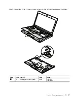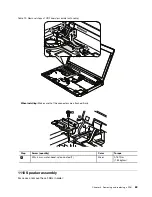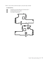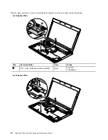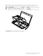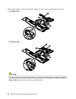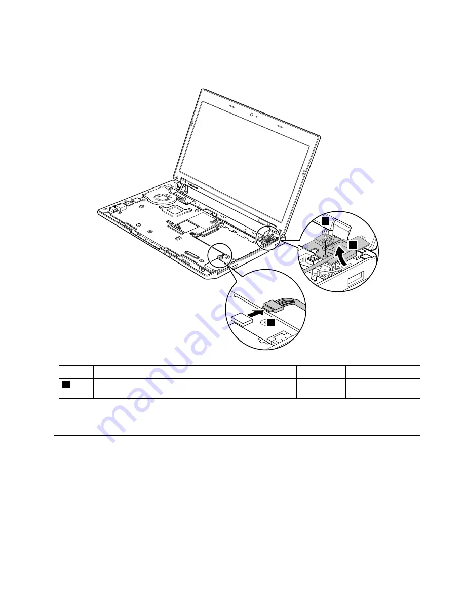
Table 21. Removal steps of I/O board
1
2
3
Step
Screw (quantity)
Color
Torque
1
M2 × 4 mm, wafer-head, nylon-coated (1)
Silver
0.181 Nm
(1.85 kgfcm)
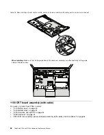
When installing:
Make sure that the connector is attached firmly.
1130 System board, fan assembly, and backup battery
Important notices for handling the system board:
When handling the system board, bear the following in mind.
• The system board has an accelerometer, which can be broken by applying several thousands of G-forces.
Note:
Dropping a system board from a height of as little as 6 inches so that it falls flat on a hard bench
can subject the accelerometer to as much as 6,000 G's of shock.
• Be careful not to drop the system board on a bench top that has a hard surface, such as metal, wood, or
composite.
• Avoid rough handling of any kind.
Chapter 8
.
Removing and replacing a FRU
71
Summary of Contents for 059624U
Page 1: ...ThinkPad X100e and X120e Hardware Maintenance Manual ...
Page 6: ...iv ThinkPad X100e and X120e Hardware Maintenance Manual ...
Page 18: ...12 ThinkPad X100e and X120e Hardware Maintenance Manual ...
Page 19: ...Chapter 1 Safety information 13 ...
Page 22: ...16 ThinkPad X100e and X120e Hardware Maintenance Manual ...
Page 26: ...20 ThinkPad X100e and X120e Hardware Maintenance Manual ...
Page 50: ...44 ThinkPad X100e and X120e Hardware Maintenance Manual ...
Page 54: ...48 ThinkPad X100e and X120e Hardware Maintenance Manual ...
Page 94: ...88 ThinkPad X100e and X120e Hardware Maintenance Manual ...
Page 120: ...LCD FRUs 1 4 3 2 5 7 6 114 ThinkPad X100e and X120e Hardware Maintenance Manual ...
Page 132: ...126 ThinkPad X100e and X120e Hardware Maintenance Manual ...
Page 135: ......
Page 136: ...Part Number 63Y0640_02 Printed in 1P P N 63Y0640_02 63Y0640_02 ...

