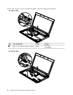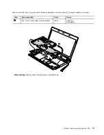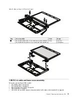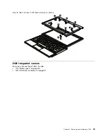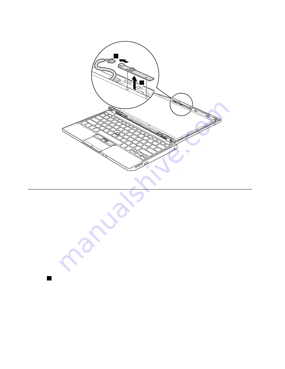
Table 27. Removal steps of integrated camera
2
1
When installing:
Make sure that the connector is attached firmly.
2030 LCD panel, hinges, and LCD cable
For access, remove these FRUs in order:
•
“1010 Battery pack” on page 50
•
“1020 Bottom door” on page 51
•
“1030 Hard disk drive (HDD)” on page 54
•
“1080 Keyboard” on page 61
•
“1090 Palm rest assembly, power-on board assembly (with cable), and microphone” on page 64
•
“1100 CRT board assembly (with cable)” on page 68
•
“1110 Speaker assembly” on page 69
•
“1120 I/O board (for ThinkPad X120e)” on page 70
•
“1130 System board, fan assembly, and backup battery” on page 71
•
“2010 LCD bezel assembly” on page 82
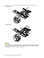
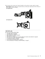
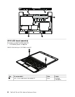
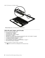
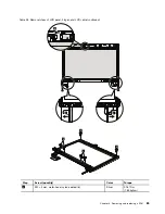
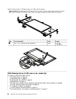
Table 28. Removal steps of LCD panel, hinges, and LCD cable
In step
1
, release the cables from the cable guide of the left and right hinges.
84
ThinkPad X100e and X120e Hardware Maintenance Manual
Summary of Contents for 059624U
Page 1: ...ThinkPad X100e and X120e Hardware Maintenance Manual ...
Page 6: ...iv ThinkPad X100e and X120e Hardware Maintenance Manual ...
Page 18: ...12 ThinkPad X100e and X120e Hardware Maintenance Manual ...
Page 19: ...Chapter 1 Safety information 13 ...
Page 22: ...16 ThinkPad X100e and X120e Hardware Maintenance Manual ...
Page 26: ...20 ThinkPad X100e and X120e Hardware Maintenance Manual ...
Page 50: ...44 ThinkPad X100e and X120e Hardware Maintenance Manual ...
Page 54: ...48 ThinkPad X100e and X120e Hardware Maintenance Manual ...
Page 94: ...88 ThinkPad X100e and X120e Hardware Maintenance Manual ...
Page 120: ...LCD FRUs 1 4 3 2 5 7 6 114 ThinkPad X100e and X120e Hardware Maintenance Manual ...
Page 132: ...126 ThinkPad X100e and X120e Hardware Maintenance Manual ...
Page 135: ......
Page 136: ...Part Number 63Y0640_02 Printed in 1P P N 63Y0640_02 63Y0640_02 ...

