•
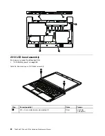
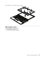
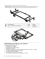
“2010 LCD bezel assembly” on page 82
•
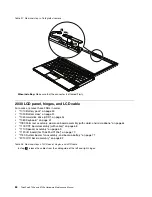
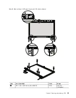
“2030 LCD panel, hinges, and LCD cable” on page 84
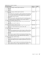
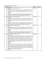
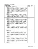
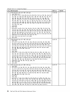
Table 29. Removal steps of antenna kit and LCD rear cover assembly
1
1
2
2
3
3
4
4
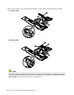
When installing:
When you install the antenna kit, route the cables as shown in the figures below. As you route the
cables, make sure that they are not subjected to any tension. Tension could cause the cables to be damaged by
the cable guides, or a wire to be broken.
a
: Wireless LAN AUX antenna (black) and wireless WAN AUX antenna (blue)
b
: Wireless LAN MAIN antenna (gray) and wireless WAN MAIN antenna (red)
a
b
Chapter 8
.
Removing and replacing a FRU
87
Summary of Contents for 059624U
Page 1: ...ThinkPad X100e and X120e Hardware Maintenance Manual ...
Page 6: ...iv ThinkPad X100e and X120e Hardware Maintenance Manual ...
Page 18: ...12 ThinkPad X100e and X120e Hardware Maintenance Manual ...
Page 19: ...Chapter 1 Safety information 13 ...
Page 22: ...16 ThinkPad X100e and X120e Hardware Maintenance Manual ...
Page 26: ...20 ThinkPad X100e and X120e Hardware Maintenance Manual ...
Page 50: ...44 ThinkPad X100e and X120e Hardware Maintenance Manual ...
Page 54: ...48 ThinkPad X100e and X120e Hardware Maintenance Manual ...
Page 94: ...88 ThinkPad X100e and X120e Hardware Maintenance Manual ...
Page 120: ...LCD FRUs 1 4 3 2 5 7 6 114 ThinkPad X100e and X120e Hardware Maintenance Manual ...
Page 132: ...126 ThinkPad X100e and X120e Hardware Maintenance Manual ...
Page 135: ......
Page 136: ...Part Number 63Y0640_02 Printed in 1P P N 63Y0640_02 63Y0640_02 ...

