background image

ThinkServer TD230
Installation and User Guide

Machine Types:

1027, 1029, 1039, and 1040

Summary of Contents for 102912U

Page 1: ...ThinkServer TD230 Installation and User Guide Machine Types 1027 1029 1039 and 1040 ...

Page 2: ......

Page 3: ...ThinkServer TD230 Installation and User Guide Machine Types 1027 1029 1039 and 1040 ...

Page 4: ... 2011 Copyright Lenovo 2010 2011 LENOVO products data computer software and services have been developed exclusively at private expense and are sold to governmental entities as commercial items as defined by 48 C F R 2 101 with limited and restricted rights to use reproduction and disclosure LIMITED AND RESTRICTED RIGHTS NOTICE If products data computer software or services are delivered pursuant ...

Page 5: ...r TD230 SATA RAID 5 Upgrade 58 Installing or removing the ThinkServer 9240 8i RAID 5 Upgrade Key 60 Installing or removing the ThinkServer Remote Management Module 3 62 Installing removing or replacing hardware devices 69 Removing or installing the ThinkServer 9240 8i RAID 0 1 Adapter 69 Removing or installing the heat sink and fan assembly 71 Removing or installing a front fan 77 Removing or inst...

Page 6: ...122 Diagnostic programs and messages 122 Diagnostic LEDs on the front panel and the system board 123 Appendix A Getting help and technical assistance 125 Before you call 125 Using the documentation 125 Getting help and information from the World Wide Web 125 Lenovo Support Web site 126 Calling for service 126 Using other services 127 Purchasing additional services 127 Lenovo product service inform...

Page 7: ...Safety information Before installing this product read the Safety Information Copyright Lenovo 2010 2011 v ...

Page 8: ...ntenance or reconfiguration of this product during an electrical storm Connect all power cords to a properly wired and grounded electrical outlet Connect to properly wired outlets any equipment that will be attached to this product When possible use one hand only to connect or disconnect signal cables Never turn on any equipment when there is evidence of fire water or structural damage Disconnect ...

Page 9: ...drives fiber optic devices or transmitters are installed note the following Do not remove the covers Removing the covers of the laser product could result in exposure to hazardous laser radiation There are no serviceable parts inside the device Use of controls or adjustments or performance of procedures other than those specified herein might result in hazardous radiation exposure DANGER Some lase...

Page 10: ...UTION Never remove the cover on a power supply or any part that has the following label attached Hazardous voltage current and energy levels are present inside any component that has this label attached There are no serviceable parts inside these components If you suspect a problem with one of these parts contact a service technician Statement 11 CAUTION The following label indicates sharp edges c...

Page 11: ...h circuit protection requirements Refer to the information that is provided with your device for electrical specifications Statement 15 CAUTION Make sure that the rack is secured properly to avoid tipping when the server unit is extended Statement 17 CAUTION The following label indicates moving parts nearby Statement 26 CAUTION Do not place any object on top of rack mounted devices Copyright Lenov...

Page 12: ...x ThinkServer TD230 Installation and User Guide ...

Page 13: ...n DVD that comes with your server To obtain the most up to date information about the server and other Lenovo products go to http www lenovo com thinkserver Record information about the server in the following table You will need these information when you register the server with Lenovo Product name ThinkServer TD230 Machine type 1027 1029 1039 or 1040 Model number _______________________________...

Page 14: ...This document provides diagnostic information parts listing replacement procedures for all CRUs and replacement procedures for other field replaceable units FRUs replaced by trained service personnel This document is in English and posted on the Lenovo Support Web site at http www lenovo com support Important Notices This document includes safety and legal notices that you are expected to read bef...

Page 15: ...and power cord Rear view on page 12 Turn on the server to verify operation Turning on the server on page 91 Review the BIOS settings and customize as needed Starting the Setup Utility program on page 95 Configure RAID RAID controllers on page 102 Check for firmware updates Using the EasyUpdate Firmware Updater program on page 109 Install operating system and basic drivers Using the ThinkServer Eas...

Page 16: ...4 ThinkServer TD230 Installation and User Guide ...

Page 17: ...cumentation the ThinkServer Documentation DVD and software media Features and specifications The following table provides information about the features and specifications of the server Depending on the server model some features might not be available or some specifications might not apply For information about your specific model use the Setup Utility program See Using the Setup Utility program ...

Page 18: ...ny performance enhancing features for the operating system environment 64 MB memory 32 MB for video memory cache Optical drive SATA DVD RW Hard disk drive expansion bays depending on model type Supports up to four 3 5 inch Serial Advanced Technology Attachment SATA or SAS hot swap hard disk drives Supports up to five 3 5 inch SATA non hot swap hard disk drives Large data storage capacity and hot s...

Page 19: ... Maximum 240 V ac Input frequency range 50 to 60 Hz Software programs Lenovo provides software to help get your server up and running EasyStartup The ThinkServer EasyStartup program simplifies the process of configuring RAID and installing supported Microsoft Windows and Linux operating systems and device drivers on your server The EasyStartup program is provided with your server on the ThinkServe...

Page 20: ...ntify problems Generating error logs for the power on self test POST failures Hot swap SAS hard disk drives Integrated Ethernet controllers Intelligent Platform Management Interface IPMI 2 0 Power on self test POST Standby voltage for system management features and monitoring System error light emitting diode LED on the front panel Vital product data VPD including the serial number information and...

Page 21: ...rols light emitting diodes LEDs and connectors Front view Figure 1 Front view of the server on page 9 shows the LEDs and parts on the front of the server Figure 1 Front view of the server 1 Power LED 4 System status LED 2 Hard disk drive status LED 5 Front door lock 3 Ethernet status LED 6 Logo plate Copyright Lenovo 2010 2011 9 ...

Page 22: ...You can open the front door with the key to locate controls LEDs connectors and other parts on the front panel Figure 2 Opening the front door 10 ThinkServer TD230 Installation and User Guide ...

Page 23: ...ptical drive eject close button 5 System status LED 11 Optical drive 6 Power button The following table describes the various meanings of the status LEDs on the front panel of your server Table 4 Meanings of the status LEDs on the front panel LED State Color Description On Green The server is on Blinking Green The server is in sleep mode Power LED Off Off The server is off Off Off The hard disk dr...

Page 24: ...ure 4 Rear view of the server on page 12 shows the locations of the connectors and parts on the rear of the server Figure 4 Rear view of the server 1 Power cord connector 5 PCI card zone 2 Serial port 6 Ethernet connector 2 3 VGA monitor connector 7 Ethernet connector 1 4 USB connectors 4 8 Front door key cut the plastic clip to get the key Connector Description Ethernet connector Used to attach a...

Page 25: ...p hard disk drive status LEDs Table 5 Hot swap hard disk drive status LEDs Hot swap hard disk drive status LED State Description On The hot swap hard disk drive is present 1 Hot swap hard disk drive present LED Off The hot swap hard disk drive is not present On The hot swap hard disk drive is active 2 Hot swap hard disk drive activity LED Off The hot swap hard disk drive is not active LEDs for the...

Page 26: ...e of the server see Removing the server cover on page 23 Figure 6 Server component locations side view without the server cover 1 Power supply assembly 9 Onboard ICH10R SATA RAID controller 2 Memory slots for microprocessor 1 some slots might with installed memory modules 10 PCI Express x4 slot 3 Optical drive 11 PCI card slot 4 Hard disk drive zone 12 PCI Express x8 slots 3 5 System fan 2 13 Heat...

Page 27: ...ATA connector 0 2 Front panel connector 19 SATA connector 1 3 Memory slot microprocessor 1 DIMM channel B1 CPU1 DIMM CHB1 20 SATA connector 2 4 Memory slot CPU1 DIMM CHB2 21 SATA connector 3 5 Memory slot CPU1 DIMM CHA1 22 SATA connector 4 6 Memory slot CPU1 DIMM CHA2 23 Internal dual port USB 2 0 connector ports 0 1 7 System fan 2 connector 24 Internal dual port USB 2 0 connector ports 2 3 8 Micr...

Page 28: ... 3 connector Locating diagnostic LEDs on the system board There are several diagnostic LEDs on the system board to help you diagnose specific problems Figure 8 Diagnostic LEDs on the system board on page 16 shows the locations of the diagnostic LEDs on the system board Figure 8 Diagnostic LEDs on the system board 1 Hard disk drive LED 7 Microprocessor 2 heat sink fan fault LED 2 System fan 3 fault...

Page 29: ...Pin position Description Pins 1 2 These pins should have a jumper in place for normal system operation default 1 J8B5 ME Force Update Pins 2 3 ME force update model Pins 1 2 BMC Firmware Force Update Mode Disabled default 2 J8C1 BMC force update Pins 2 3 BMC Firmware Force Update Mode Enabled Pins 1 2 These pins should have a jumper in place for normal system operation default 3 J1A1 BIOS recovery...

Page 30: ...l be cleared on the next reset These pins should not be jumpered for normal operation Note Before clearing the CMOS turn off the server and disconnect the power cord Move the jumper from pins 1 2 to pins 2 3 Wait more than five minutes then move the jumper back to the normal position pins 1 2 is short circuited to clear CMOS Locating connectors on the hot swap hard disk drive backplanes There are ...

Page 31: ...ctor 3 8 Hot swap hard disk drive 0 connector 3 Power connector 9 First hot swap hard disk drive backplane 4 Hot swap hard disk drive 3 connector 10 SATA SAS signal connector 1 5 Hot swap hard disk drive 2 connector 11 SATA SAS signal connector 0 6 Power connector 12 Second hot swap hard disk drive backplane Chapter 4 Locating parts controls LEDs and connectors 19 ...

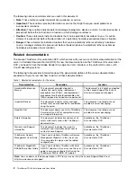
Page 32: ...20 ThinkServer TD230 Installation and User Guide ...

Page 33: ...e updates for your server do the following 1 Go to http www lenovo com support 2 Click Download Drivers ThinkServer and then follow the instructions on the Web page to download firmware updates for your server Before you install optional hardware devices make sure that the server is working correctly If an operating system is installed turn on the server and make sure that the operating system sta...

Page 34: ...erly route the cables For some options such as PCI cards follow the cabling instructions that come with the options Make sure that you replace a failed fan within 48 hours When replacing a hot swap drive install the new hot swap drive within two minutes of removal Do not remove any air duct or air baffles while the server is running Operating the server without the air duct or air baffles might ca...

Page 35: ...inks while you are working inside the server Do not allow your necktie or scarf to hang inside the server Remove jewelry such as bracelets necklaces rings and loose fitting wrist watches Remove items from your shirt pocket such as pens and pencils These items might fall into the server as you lean over it Avoid dropping any metallic objects into the server such as paper clips hairpins and screws R...

Page 36: ... two thumbscrews are securely installed and you need to use a tool for example a screw driver to loosen the thumbscrews b The two thumbscrews are integrated parts of the server cover and they cannot be removed from the server cover Figure 11 Sliding the server cover to the rear 24 ThinkServer TD230 Installation and User Guide ...

Page 37: ...ion DVD that came with your product and Guidelines on page 21 To obtain a copy of the publications go to http www lenovo com support This section provides instructions on how to remove and reinstall the front bezel To remove and reinstall the front bezel do the following 1 Remove all media from the drives and turn off all attached devices and the server Then disconnect all power cords from electri...

Page 38: ...e left side 5 Go to Completing the parts replacement on page 90 Locking or unlocking the hard disk drive side door Attention Do not open your server or attempt any repair before reading and understanding the Safety Information and the Warranty and Support Information on the ThinkServer Documentation DVD that came with your product and Guidelines on page 21 To obtain a copy of the publications go t...

Page 39: ...side door to ensure that all the hard disk drives cannot be accessed unless you remove the server cover If you do so you must turn off the server disconnect all power cords and remove the server cover when you want to replace any hard disk drives including the hot swap hard disk drives To lock or unlock the hard disk drive side door do the following 1 Press the blue button 1 to open the side door ...

Page 40: ... door to the closed position Then close the side door until it snaps into position The side door is locked and cannot be opened when you press the blue button Figure 15 Locking the side door 28 ThinkServer TD230 Installation and User Guide ...

Page 41: ... procedure for the optional hardware device that you want to replace Installing or removing a memory module This section provides instructions on how to install or remove a memory module For a list of the supported memory modules for your server go to http www lenovo com thinkserver On the ThinkServer systems page click Products Options ThinkServer Memory Memory module installation rules Your serv...

Page 42: ...e with your product and Guidelines on page 21 To obtain a copy of the publications go to http www lenovo com support This section provides instructions on how to install a memory module To install a memory module do the following 1 Remove all media from the drives and turn off all attached devices and the server Then disconnect all power cords from electrical outlets and disconnect all cables that...

Page 43: ...sition Note If there is a gap between the memory module and the retaining clips the memory module has not been correctly installed Open the retaining clips remove the memory module and then reinstall it into the slot Figure 18 Installing the memory module What to do next To work with another piece of hardware go to the appropriate section To complete the installation or replacement go to Completin...

Page 44: ...ons on how to remove or install internal drives for the server See Features and specifications on page 5 for information about the types of internal drives that the server supports and see Locating server components on page 14 for the locations of the drive bays in the server When installing an internal drive be sure to consider the following information Make sure that you have all the cables and ...

Page 45: ... copy of the publications go to http www lenovo com support This section provides instructions on how to remove the optical drive To remove the optical drive do the following 1 Remove all media from the drives and turn off all attached devices and the server Then disconnect all power cords from electrical outlets and disconnect all cables that are connected to the server 2 Remove the server cover ...

Page 46: ...e out of the front of the server Figure 20 Removing the optical drive 6 Remove the optical drive retainers from both sides of the old optical drive and save them to use when you install a new optical drive Figure 21 Removing the optical drive retainers 34 ThinkServer TD230 Installation and User Guide ...

Page 47: ...rive You have removed the optical drive retainers from both sides of the old optical drive and have them available for installation on the new optical drive Note If you are installing a laser device such as a drive observe the following safety precautions Statement 3 CAUTION When laser products such as CD ROMs DVD drives fiber optic devices or transmitters are installed note the following Do not r...

Page 48: ...e and place it on a static protective surface 6 Install the optical drive retainers on both sides of the new optical drive Note Note the orientation of the optical drive retainers and the corresponding holes in both sides of the optical drive when installing the retainers Figure 22 Installing the optical drive retainers 36 ThinkServer TD230 Installation and User Guide ...

Page 49: ...he new optical drive and the other end to an available SATA connector SATA connector 5 recommended on the system board See Locating parts on the system board on page 15 Then locate an available five wire power connector 1 and connect it to the rear of the new optical drive Figure 24 Connecting the optical drive cables Chapter 5 Installing removing or replacing hardware 37 ...

Page 50: ...on applies only to server models that have hot swap hard disk drives installed Attention To maintain proper system cooling do not operate the server for more than 10 minutes without either a drive or a filler panel installed in each drive bay To remove a hot swap hard disk drive do the following Note You do not have to turn off the server when removing a hot swap hard disk drive However if you hav...

Page 51: ...t to remove Then press the blue release button 1 and rotate the handle of the hard disk drive bracket to the open position Figure 26 Opening the handle of the hot swap hard disk drive bracket Chapter 5 Installing removing or replacing hardware 39 ...

Page 52: ...le 1 and pull the hard disk drive bracket with the hard disk drive out of the drive bay Figure 27 Removing the hot swap hard disk drive bracket with the hard disk drive 40 ThinkServer TD230 Installation and User Guide ...

Page 53: ...in a copy of the publications go to http www lenovo com support This section provides instructions on how to install a hot swap hard disk drive This section applies only to server models that support hot swap hard disk drives Attention To maintain proper system cooling do not operate the server for more than 10 minutes without either a drive or a filler panel installed in each drive bay To install...

Page 54: ...1 Press the blue button 1 to open the side door Figure 29 Opening the side door 42 ThinkServer TD230 Installation and User Guide ...

Page 55: ...to install the drive Then press the blue release button 1 and rotate the handle of the hard disk drive bracket to the open position Figure 30 Opening the handle of the hot swap hard disk drive bracket Chapter 5 Installing removing or replacing hardware 43 ...

Page 56: ...rd save the EMC shield or drive bay filler from the drive bay or save the PCI card slot cover in the event that you later remove the device An unoccupied drive bay or PCI card slot without cover shield filler or any other protection might impact the EMI integrity and cooling of the server which might result in overheating or component damage 5 Touch the static protective package that contains the ...

Page 57: ... touching the circuit board on the bottom of the hard disk drive Figure 32 Installing the hard disk drive into the bracket 7 Keep the handle of the hot swap hard disk drive bracket fully open and then slide the bracket with the hard disk drive into the drive bay until it cannot be pushed in anymore Figure 33 Sliding the hot swap hard disk drive bracket with the hard disk drive into the bay Chapter...

Page 58: ...ognized If the amber hard disk drive status LED is lit continuously this indicates that the hard disk drive is faulty and must be replaced if the green hard disk drive status LED is blinking this indicates that the hard disk drive is operating correctly Note If the server is configured for RAID operation using a RAID controller you might have to reconfigure the disk arrays after you replace hard d...

Page 59: ... the server for more than 10 minutes without either a drive or a filler panel installed in each drive bay To remove a non hot swap hard disk drive do the following 1 Remove all media from the drives and turn off all attached devices and the server Then disconnect all power cords from electrical outlets and disconnect all cables that are connected to the server 2 Press the blue button 1 to open the...

Page 60: ...le of the hard disk drive bracket to slide the bracket with the hard disk drive out of the drive bay Figure 36 Disconnecting cables and sliding the non hot swap hard disk drive out 4 Depending on the non hot swap hard disk drive is secured in the bracket by screws or plastic retainers do one of the following 48 ThinkServer TD230 Installation and User Guide ...

Page 61: ...erials that are supplied to you for shipping What to do next To work with another piece of hardware go to the appropriate section To complete the removal procedure go to Completing the parts replacement on page 90 Installing a non hot swap hard disk drive Attention Do not open your server or attempt any repair before reading and understanding the Safety Information and the Warranty and Support Inf...

Page 62: ...t all power cords from electrical outlets and disconnect all cables that are connected to the server 2 Press the blue button 1 to open the side door Note If you have locked the side door you must turn off the server disconnect all power cords and remove the server cover when you want to remove install or replace any hard disk drives See Locking or unlocking the hard disk drive side door on page 26...

Page 63: ...the PCI card slot cover in the event that you later remove the device An unoccupied drive bay or PCI card slot without cover shield filler or any other protection might impact the EMI integrity and cooling of the server which might result in overheating or component damage 5 Touch the static protective package that contains the new hard disk drive to any unpainted metal surface on the server Then ...

Page 64: ... Figure 41 Securing the hard disk drive in the bracket by screws If you want to secure the hard disk drive in the bracket by retainers align the holes in both sides of the hard disk drive with the corresponding holes in the bracket Then carefully install the retainers 1 on both sides to secure the hard disk drive in the bracket Figure 42 Securing the hard disk drive in the bracket by retainers 52 ...

Page 65: ... hard disk drive is faulty and must be replaced if the green hard disk drive status LED is blinking this indicates that the hard disk drive is operating correctly Note If the server is configured for RAID operation using a RAID controller you might have to reconfigure the disk arrays after you replace hard disk drives Installing or removing a PCI card This section provides instructions on how to i...

Page 66: ...ll media from the drives and turn off all attached devices and the server Then disconnect all power cords from electrical outlets and disconnect all cables that are connected to the server 2 Remove the server cover See Removing the server cover on page 23 3 Lay the server on its side for easier operation 4 Locate an appropriate PCI card slot on the system board See Locating parts on the system boa...

Page 67: ...ece of hardware go to the appropriate section To complete the installation go to Completing the parts replacement on page 90 Removing a PCI card Attention Do not open your server or attempt any repair before reading and understanding the Safety Information and the Warranty and Support Information on the ThinkServer Documentation DVD that came with your product and Guidelines on page 21 To obtain a...

Page 68: ...board 5 Remove the screw that secures the PCI card Then grasp the PCI card by the edges and carefully pull it out of the PCI card slot If necessary alternate moving each side of the PCI card a small and equal amount until it is completely removed from the slot Figure 45 Removing a PCI card If you are instructed to return the removed PCI card to the manufacturer follow all packaging instructions an...

Page 69: ...ation go to Completing the parts replacement on page 90 On Linux operating systems you do not need to install any device driver for the Ethernet card on Windows operating systems you need to install the device driver for the Ethernet card To install the device driver on Windows operating systems do the following 1 Save any open documents and exit all applications 2 Insert the ThinkServer EasyStart...

Page 70: ...u can install on the system board to enable the RAID 5 configuration function of the onboard SATA RAID for your server Installing the RAID 5 key Attention Do not open your server or attempt any repair before reading and understanding the Safety Information and the Warranty and Support Information on the ThinkServer Documentation DVD that came with your product and Guidelines on page 21 To obtain a...

Page 71: ... instructions on how to remove the RAID 5 key from the system board If you remove the RAID 5 key the RAID 5 configuration function of the onboard SATA RAID becomes unavailable However the RAID 5 configuration function of the ThinkServer 9240 8i RAID 0 1 Adapter is still available if you have installed the ThinkServer 9240 8i RAID 5 Upgrade Key on the adapter See Installing the 9240 8i RAID 5 key o...

Page 72: ...nfiguration function for this adapter you need to install the 9240 8i RAID 5 key on the adapter Installing the 9240 8i RAID 5 key Attention Do not open your server or attempt any repair before reading and understanding the Safety Information and the Warranty and Support Information on the ThinkServer Documentation DVD that came with your product and Guidelines on page 21 To obtain a copy of the pu...

Page 73: ...lines on page 21 To obtain a copy of the publications go to http www lenovo com support This section provides instructions on how to remove the 9240 8i RAID 5 key from the ThinkServer 9240 8i RAID 0 1 Adapter If you remove the 9240 8i RAID 5 key the RAID 5 configuration function of the ThinkServer 9240 8i RAID 0 1 Adapter becomes unavailable However the RAID 5 configuration function of the onboard...

Page 74: ...urer follow all packaging instructions and use any packaging materials that are supplied to you for shipping What to do next To work with another piece of hardware go to the appropriate section To complete the removal procedure go to Completing the parts replacement on page 90 Installing or removing the ThinkServer Remote Management Module 3 This section provides product information about the Thin...

Page 75: ...r or attempt any repair before reading and understanding the Safety Information and the Warranty and Support Information on the ThinkServer Documentation DVD that came with your product and Guidelines on page 21 To obtain a copy of the publications go to http www lenovo com support This section provides instructions on how to install the RMM3 in your server You can get an increased level of manage...

Page 76: ... screw when installing the RMM3 Figure 51 Removing the PCI card slot bracket for the RMM3 connector 6 Touch the static protective package that contains the RMM3 to any unpainted surface on the outside of the server Then remove the RMM3 from the package 7 Make a note of the Media Access Controller MAC address of the RMM3 This information is on a label attached to the RMM3 and might be used later fo...

Page 77: ...cure the RMM3 to the slot bracket Notes a There are three screws in the option package and you only need to use two of them to secure the RMM3 to the slot bracket The extra one is a backup screw b For easier operation you might need to attach a plastic standoff that came with the option package to each screw before installing the screw Figure 52 Installing the RMM3 on the slot bracket Chapter 5 In...

Page 78: ...or the PCI card slot bracket you have removed Then secure the slot bracket with RMM3 in place by installing the screw that you have removed in step 5 on page 64 Figure 53 Installing the slot bracket with RMM3 66 ThinkServer TD230 Installation and User Guide ...

Page 79: ...ork interface controller then configure the RMM3 by referring to the ThinkServer Remote Management User Guide on the ThinkServer Documentation DVD that came with your product Removing the RMM3 Attention Do not open your server or attempt any repair before reading and understanding the Safety Information and the Warranty and Support Information on the ThinkServer Documentation DVD that came with yo...

Page 80: ...e ribbon cable from the RMM3 connector on the system board See Locating parts on the system board on page 15 Remove the screw that secures the slot bracket with RMM3 Then carefully lift the slot bracket with RMM3 out of the server Figure 55 Disconnecting the ribbon cable and removing the slot bracket with RMM3 5 Put the removed RMM3 kit slot bracket with RMM3 and ribbon cable into its original pac...

Page 81: ...you will loose all the current RAID configuration based on the RAID card Note This section only applies to server models with hot swap hard disk drives To remove the RAID card do the following 1 Remove all media from the drives and turn off all attached devices and the server Then disconnect all power cords from electrical outlets and disconnect all cables that are connected to the server 2 Remove...

Page 82: ...installed into the appropriate PCI Express x8 slot on the system board callout 31 in Figure 7 Locating major parts on the system board on page 15 See Locating parts on the system board on page 15 5 Touch the static protective package that contains the RAID card to any unpainted surface on the outside of the server Then remove the RAID card from the package 6 Depending on your RAID card you might n...

Page 83: ...dware go to the appropriate section To complete the installation go to Completing the parts replacement on page 90 Then refer to Chapter 6 Configuring the server on page 95 for information about RAID configuration Removing or installing the heat sink and fan assembly This section provides instructions on how to remove or install the heat sink and fan assembly Removing the heat sink and fan assembl...

Page 84: ...ect all power cords from electrical outlets and disconnect all cables that are connected to the server 2 Remove the server cover See Removing the server cover on page 23 3 Locate the heat sink and fan assembly See Locating server components on page 14 Note If a second microprocessor is installed in the server there will also be a heat sink and fan assembly installed above the second microprocessor...

Page 85: ...n remove the four screws 1 that secure the heat sink and fan assembly Note Carefully remove the four screws from the system board to avoid any possible damage The four screws are integrated parts of the heat sink and fan assembly and they cannot be removed from the heat sink and fan assembly Figure 57 Screws that secure the heat sink and fan assembly for microprocessor 1 Chapter 5 Installing remov...

Page 86: ... and fan assembly for microprocessor 2 6 Lift the heat sink and fan assembly off the system board Notes a You might have to gently twist the heat sink and fan assembly to free it from the microprocessor b When handling the heat sink and fan assembly do not touch the thermal grease 1 on the bottom of it Figure 59 Heat sink and fan assembly 7 If you are instructed to return the removed heat sink and...

Page 87: ...s section provides instructions on how to install the heat sink and fan assembly DANGER Hazardous moving parts Keep fingers and other body parts away CAUTION The heat sink and microprocessor might be very hot Turn off the server and wait three to five minutes to let the server cool before removing the server cover To install the heat sink and fan assembly do the following 1 Remove all media from t...

Page 88: ...painted surface on the outside of the server Then remove the heat sink and fan assembly from the package Note When handling the heat sink and fan assembly do not touch the thermal grease 1 on the bottom of it Figure 60 Heat sink and fan assembly 76 ThinkServer TD230 Installation and User Guide ...

Page 89: ...ear of the chassis Figure 61 Screws that secure the heat sink and fan assembly for microprocessor 1 Figure 62 Screws that secure the heat sink and fan assembly for microprocessor 2 6 Alternate tightening each screw a small and equal amount until the heat sink and fan assembly is secured to the system board Do not over tighten the screws 7 Connect the heat sink and fan assembly cable to the system ...

Page 90: ... attached devices and the server Then disconnect all power cords from electrical outlets and disconnect all cables that are connected to the server 2 Remove the server cover See Removing the server cover on page 23 3 Locate the front fan that you want to remove See Locating server components on page 14 Note If two microprocessors are installed in your server there are two front fans one for microp...

Page 91: ...g materials that are supplied to you for shipping What to do next To work with another piece of hardware go to the appropriate section To complete the removal procedure go to Completing the parts replacement on page 90 Installing a front fan Attention Do not open your server or attempt any repair before reading and understanding the Safety Information and the Warranty and Support Information on th...

Page 92: ...and the server Then disconnect all power cords from electrical outlets and disconnect all cables that are connected to the server 2 Remove the server cover See Removing the server cover on page 23 3 Remove the hard disk drives See Removing a hot swap hard disk drive on page 38 or Removing a non hot swap hard disk drive on page 47 80 ThinkServer TD230 Installation and User Guide ...

Page 93: ...nts through the holes from the other side to secure the front fan in place Figure 64 Installing the front fan 5 Connect the front fan cable to the corresponding front fan connector on the system board See Locating parts on the system board on page 15 6 Reinstall all hard disk drives See Installing a hot swap hard disk drive on page 41 or Installing a non hot swap hard disk drive on page 49 What to...

Page 94: ...des instructions on how to remove the rear fan DANGER Hazardous moving parts Keep fingers and other body parts away To remove the rear fan do the following 1 Remove all media from the drives and turn off all attached devices and the server Then disconnect all power cords from electrical outlets and disconnect all cables that are connected to the server 2 Remove the server cover See Removing the se...

Page 95: ... To work with another piece of hardware go to the appropriate section To install the rear fan see Installing the rear fan on page 83 Installing the rear fan Attention Do not open your server or attempt any repair before reading and understanding the Safety Information and the Warranty and Support Information on the ThinkServer Documentation DVD that came with your product and Guidelines on page 21...

Page 96: ... Remove all media from the drives and turn off all attached devices and the server Then disconnect all power cords from electrical outlets and disconnect all cables that are connected to the server 2 Remove the server cover See Removing the server cover on page 23 84 ThinkServer TD230 Installation and User Guide ...

Page 97: ...er mounts through the holes from the other side of the chassis to secure the rear fan in place Figure 66 Installing the rear fan 4 Connect the rear fan cable to the system fan 3 connector on the system board See Locating parts on the system board on page 15 What to do next To work with another piece of hardware go to the appropriate section To complete the installation go to Completing the parts r...

Page 98: ...r do the following 1 Remove all media from the drives and turn off all attached devices and the server Then disconnect all power cords from electrical outlets and disconnect all cables that are connected to the server 2 Remove the server cover See Removing the server cover on page 23 3 Lay the server on its side for easier operation 4 Remove the heat sink and fan assembly See Removing the heat sin...

Page 99: ...stalled both must have the same core voltage and core speed 2 When only one microprocessor is installed it must be in the microprocessor 1 socket The other socket must be empty 3 Always install the microprocessor first into the microprocessor 1 socket and then install another microprocessor into the microprocessor 2 socket if you want to install two microprocessors To install the microprocessor do...

Page 100: ...rocessor socket To avoid damaging the pins in the microprocessor socket do not touch the pins while removing the cover Figure 70 Removing the microprocessor socket cover 8 Remove the new microprocessor from the protective cover that protects the gold contacts on the bottom of the new microprocessor 88 ThinkServer TD230 Installation and User Guide ...

Page 101: ... type of memory that maintains the date time and configuration information for built in features The system board battery keeps this information active when you turn off the server The system board battery normally requires no charging or maintenance throughout its life however no battery lasts forever If the system board battery fails the date time and configuration information including password...

Page 102: ...rd battery and remove it from the socket Figure 72 Removing the system board battery 6 Follow any special handling and installation instructions that came with the new system board battery and install the new system board battery into its socket Make sure that the battery clip securely holds the battery Note Note the orientation of the system board battery when you install it into the socket Figur...

Page 103: ...ast If the server cables and connector panel have color coded connections match the color of the cable end with the color of the connector For example match a blue cable end with a blue panel connector a red cable end with a red connector and so on See Rear view on page 12 for an illustration of the I O connectors on the rear of the server Turning on the server When the server is connected to an a...

Page 104: ...lowing ways You can turn off the server from the operating system if your operating system supports this feature After an orderly shutdown of the operating system the server will turn off automatically You can press the power button to start an orderly shutdown of the operating system and turn off the server if your operating system supports this feature If the operating system stops functioning y...

Page 105: ...3 Follow the instructions that come with the device to prepare it for installation and to connect it to the server Chapter 5 Installing removing or replacing hardware 93 ...

Page 106: ...94 ThinkServer TD230 Installation and User Guide ...

Page 107: ...it For information about using this program see the MegaRAID SAS Software User Guide on the ThinkServer Documentation DVD that came with you server The following table lists the different server configurations and the applications that are available for configuring and managing RAID arrays Table 9 Server configurations and applications for configuring and managing RAID arrays Server configuration ...

Page 108: ...s to clear CMOS and recover to the factory default settings 2 If you have changed any hardware except the hard disk drives in the server you must reflash the BIOS the BMC firmware and the FRU SDR Introduction of the BIOS items The following tables list all the main menus and items in the Setup Utility program Some items might vary because of the BIOS updates Notes 1 Use the default setting for any...

Page 109: ... the Processor Configuration on page 98 Memory Configuration Enter the submenu to see all the options See Table 14 Submenus under the Memory Configuration on page 98 Mass Storage Controller Configuration Enter the submenu to see all the options See Table 16 Submenus under the Mass Storage Controller Configuration on page 99 Serial Port Configuration Enter the submenu to see all the options See Tab...

Page 110: ... for Directed I O Disabled Enabled Enable or disable the Intel Virtualization Tech for I O devices Hardware Prefetcher Disabled Enabled Enable or disable the prefetch function of the microprocessor This setting might impact system performance Adjacent Cache Line Prefetch Disabled Enabled Enable or disable the adjacent cache line prefetch This setting might impact system performance Direct Cache Ac...

Page 111: ...he serial port 1 I O address IRQ 3 4 Select the serial port 1 I O interruption Serial B Enable Disabled Enabled Enable or disable the serial port 2 I O Address 3F8 2F8 3E8 2E8 Select the serial port 2 I O address IRQ 3 4 Select the serial port 2 I O interruption Note The settings in are the default settings in the Setup Utility program Table 18 Submenus under the USB Configuration Item Option Desc...

Page 112: ...n the Setup Utility program Table 21 Items under the Security menu Item Option Description Set Administrator Password Set or change the administrator password The password can be any combination of up to 7 1 to 7 alphabetic and numeric characters Set User Password Set or change the user password The password can be any combination of up to 7 1 to 7 alphabetic and numeric characters Front Panel Loc...

Page 113: ...d boot device Boot Option 3 Use this option to set the third boot device Boot Option 4 Use this option to set the fourth boot device Network Device Order Use this option to set the network device boot sequence Delete Boot Option Delete boot options EFI Optimized Boot Disabled Enabled Boot Option Retry Disabled Enabled Note The settings in are the default settings in the Setup Utility program Exiti...

Page 114: ...evious passwords Setting changing or deleting a password This section provides instructions on how to set change or delete a password To set change or delete a password do the following 1 Start the Setup Utility program See Starting the Setup Utility program on page 95 2 From the Setup Utility program main menu select Security Set Administrator Password or Set User Password For information about t...

Page 115: ...AID SAS Software User Guide on the ThinkServer Documentation DVD that came with you server or download the publication from the Lenovo Support Web site at http www lenovo com support And you can find and install the MegaCLI program and the MegaRAID Storage Manager program in the ThinkServer EasyStartup DVD that came with your server Insert the DVD into the optical drive and the files are in the To...

Page 116: ...the EasyStartup program to install an operating system make sure any external storage devices and fiber channels are configured correctly Setup and configuration When you start the ThinkServer EasyStartup DVD you will be prompted for the following Select the language in which you want to view the program Select the language of the keyboard you will be using with the program Note The following lang...

Page 117: ...you select Install operating system you will be prompted for information required for the installation The prompts vary depending on the operating system selected This section describes the tasks associated with a typical Windows operating system installation Each task must be completed in order before moving to the next task Note Ensure that your RAID controller is correctly configured before you...

Page 118: ...1 During the POST when you see the message Press Ctrl E to enter Embedded RAID II Configuration Utility press Ctrl E to enter the main menu for the SATA RAID configuration program 2 Follow the instructions on the screen to configure the SATA RAID When working with this program you must use the keyboard The keys used to perform various tasks are displayed at the bottom of each screen The main menu ...

Page 119: ...n menu opens 7 Select the RAID array you want to create and press Enter 8 Set the stripe size for the new array Then select ACCEPT and press Enter Note If you are creating a RAID volume by using the New Configuration option you can also set the volume capacity 9 Follow the instructions on the screen to finish all settings Then press Esc to exit the program When prompted select Yes and press Enter ...

Page 120: ... Drive from the main menu 2 Use the space key to select the hard disk drive that needs to be rebuilt 3 Press F10 When prompted select Yes to start rebuilding The hard disk drive status will be shown as REBUILD 4 After finish rebuilding press any key to continue other operations you want to do Checking the RAID 1 volume consistency Checking the consistency of the RAID volume helps you find the prob...

Page 121: ...oftware RAID firmware is integrated into the BIOS ROM on the system board The SAS RAID card firmware is stored in ROM on the SAS RAID card The Ethernet firmware is downloadable at http www lenovo com support Using the EasyUpdate Firmware Updater program ThinkServer EasyUpdate Firmware Updater is a software application that enables you to maintain your system firmware up to date and helps you avoid...

Page 122: ... ThinkServer EasyManage Agent you must already have a core server running the ThinkServer EasyManage Core Server program The ThinkServer EasyManage Agent must be installed from that core server Refer to the ThinkServer EasyManage Core Server documentation about Agent deployment for instructions on the various ways to deploy the ThinkServer EasyManage Agent to your new server Also the ThinkServer E...

Page 123: ...em is solved See the parts listing in the Hardware Maintenance Manual to determine which components are customer replaceable units CRUs and which components are field replaceable units FRUs If an action step is preceded by Trained service technician only that step must be performed only by a trained service technician Symptom Action The DVD drive is not recognized 1 Make sure that The SATA channel...

Page 124: ...RUs If an action step is preceded by Trained service technician only that step must be performed only by a trained service technician Symptom Action Not all drives are recognized by the hard disk drive diagnostic tests Remove the drive that is indicated by the diagnostic tests then run the hard disk drive diagnostic tests again If the remaining drives are recognized replace the drive that you remo...

Page 125: ...ompatible with the server Refer to the Web site at http www lenovo com thinkserver 3 If you are using a USB keyboard and it is connected to a USB hub disconnect the keyboard from the hub and connect it directly to the server 4 Replace the following components one at a time in the order shown restarting the server each time a Keyboard b Trained service technician only System board The mouse or poin...

Page 126: ...guration 4 Add one pair of DIMMs at a time making sure that the DIMMs in each pair are matching 5 Reseat the DIMMs 6 Replace the DIMMs in step 5 on page 114 one at a time in the order shown restarting the server each time Multiple rows of DIMMs in a branch are identified as failing 1 Reseat the DIMMs then restart the server 2 Replace the lowest numbered DIMMs with identical known good DIMMs then r...

Page 127: ...and adjusting the monitor Follow the suggested actions in the order in which they are listed in the Action column until the problem is solved See the parts listing in the Hardware Maintenance Manual to determine which components are customer replaceable units CRUs and which components are field replaceable units FRUs If an action step is preceded by Trained service technician only that step must b...

Page 128: ...ace the following components one at a time in the order shown restarting the server each time a Monitor b Trained service technician only System board Optional device problems Follow the suggested actions in the order in which they are listed in the Action column until the problem is solved See the parts listing in the Hardware Maintenance Manual to determine which components are customer replacea...

Page 129: ...ed correctly Any external SCSI device is turned on You must turn on an external SCSI device before you turn on the server 4 Reseat the failing device 5 Replace the failing device Power problems Follow the suggested actions in the order in which they are listed in the Action column until the problem is solved See the parts listing in the Hardware Maintenance Manual to determine which components are...

Page 130: ...each time a DIMMs b Trained service technician only Power switch connector c Trained service technician only Power backplane d Trained service technician only System board 5 If you just installed an optional device remove it and restart the server If the server now starts you might have installed more devices than the power supply supports 6 See Solving undetermined problems on page 121 The server...

Page 131: ...ach time a Failing serial device b Serial cable c Trained service technician only System board Software problems Follow the suggested actions in the order in which they are listed in the Action column until the problem is solved See the parts listing in the Hardware Maintenance Manual to determine which components are customer replaceable units CRUs and which components are field replaceable units...

Page 132: ... power cords 2 Check for loose cables in the power subsystem Also check for short circuits for example if a loose screw is causing a short circuit on a circuit board 3 Remove the adapters and disconnect the cables and power cords to all internal and external devices until the server is at the minimum configuration that is required for the server to start see Solving undetermined problems on page 1...

Page 133: ...tocol If the Ethernet controller still cannot connect to the network but the hardware appears to be working the network administrator must investigate other possible causes of the error Solving undetermined problems If the diagnostic tests did not diagnose the failure or if the server is inoperative use the information in this section If you suspect that a software problem is causing failures cont...

Page 134: ...bility to display progress codes a progress code can be customized to fit the data width The higher the data bit the higher the granularity of information that can be sent on the progress port The progress codes may be reported by the system BIOS or option ROMs The response has three types Minor The message displays on the screen or on the Error Manager screen and an error is logged to the SEL The...

Page 135: ...fying the diagnostic LEDs on the front panel and the system board is a very important method for diagnosing server problems See Front view on page 9 and Locating diagnostic LEDs on the system board on page 16 for detailed information Chapter 7 Troubleshooting 123 ...

Page 136: ...124 ThinkServer TD230 Installation and User Guide ...

Page 137: ... also describes the diagnostic tests that you can perform Most systems operating systems and programs come with documentation that contains troubleshooting procedures and explanations of error messages and error codes If you suspect a software problem see the documentation for the operating system or program Using the documentation Information about your Lenovo system and preinstalled software if ...

Page 138: ...ersonnel are available to provide the applicable level of service Engineering Change management There might be changes that are required after a product has been sold Lenovo or your reseller will make selected Engineering Changes ECs available that apply to your hardware These items are not covered by the warranty Replacement or use of parts not manufactured for or by Lenovo or non warranted Lenov...

Page 139: ...e all models of a particular machine type In some countries fees and restrictions might apply at the time of service To determine whether your computer is eligible for International Warranty Service and to view a list of the countries where service is available go to http www lenovo com support click Warranty and follow the instructions on the screen For technical assistance with the installation ...

Page 140: ...128 ThinkServer TD230 Installation and User Guide ...

Page 141: ...ublication Lenovo may make improvements and or changes in the product s and or the program s described in this publication at any time without notice The products described in this document are not intended for use in implantation or other life support applications where malfunction may result in injury or death to persons The information contained in this document does not affect or change Lenovo...

Page 142: ...ternal hard disk drive capacities assume the replacement of any standard hard disk drives and population of all hard disk drive bays with the largest currently supported drives that are available from Lenovo Maximum memory might require replacement of the standard memory with an optional memory module Lenovo makes no representation or warranties regarding non Lenovo products and services including...

Page 143: ...péré en fin de vie In accordance with the European WEEE Directive electrical and electronic equipment EEE is to be collected separately and to be reused recycled or recovered at end of life Users of EEE with the WEEE marking per Annex IV of the WEEE Directive as shown above must not dispose of end of life EEE as unsorted municipal waste but use the collection framework available to customers for t...

Page 144: ...on rate of less than 300 Å in 30 days 1 ASHRAE 52 2 2008 Method of Testing General Ventilation Air Cleaning Devices for Removal Efficiency by Particle Size Atlanta American Society of Heating Refrigerating and Air Conditioning Engineers Inc 2 The deliquescent relative humidity of particulate contamination is the relative humidity at which the dust absorbs enough water to become wet and promote ion...

Page 145: ... EC batteries and accumulators are labeled to indicate that they are to be collected separately and recycled at end of life The label on the battery may also include a chemical symbol for the metal concerned in the battery Pb for lead Hg for mercury and Cd for cadmium Users of batteries and accumulators must not dispose of batteries and accumulators as unsorted municipal waste but use the collecti...

Page 146: ... This device complies with Part 15 of the FCC Rules Operation is subject to the following two conditions 1 this device may not cause harmful interference and 2 this device must accept any interference received including interference that may cause undesired operation Industry Canada Class A emission compliance statement This Class A digital apparatus complies with Canadian ICES 003 Cet appareil nu...

Page 147: ...desrepublik Deutschland Zulassungsbescheinigung laut dem Deutschen Gesetz über die elektromagnetische Verträglichkeit von Betriebsmitteln EMVG vom 20 Juli 2007 früher Gesetz über die elektromagnetische Verträglichkeit von Geräten bzw der EMV EG Richtlinie 2004 108 EC früher 89 336 EWG für Geräte der Klasse A Dieses Gerät ist berechtigt in Übereinstimmung mit dem Deutschen EMVG das EG Konformitätsz...

Page 148: ...pliance statement for products which connect to the power mains with rated current less than or equal to 20 A per phase China Class A compliance statement Taiwan Class A compliance statement Lenovo product service information for Taiwan 136 ThinkServer TD230 Installation and User Guide ...

Page 149: ...s 122 DIMM installing 30 problems 113 removing 31 display problems 115 drive bays internal 32 drives hot swap removing 38 non hot swap removing 47 DVD drive problems 111 error symptoms 111 E EasyStartup using 103 error symptoms CD ROM drive DVD ROM drive 111 general 112 hard disk drive 112 intermittent 112 keyboard non USB 113 memory 113 microprocessor 114 monitor 115 mouse non USB 113 optional de...

Page 150: ...ve 49 optical drive 35 PCI card 54 RAID 5 key 58 RAID card 70 rear fan 83 RMM3 63 server cover 91 integrated functions 7 intermittent problems 112 internal drives installing 32 removing 32 K keyboard problems 113 L LEDs rear of the server 12 LEDs and controls on the front of the server 9 locating connectors backplane 18 logs system event message 122 M memory module installation order 29 installati...

Page 151: ...SAS or SATA hard disk drives 47 optical drive 33 PCI card 55 RAID 5 key 59 RAID card 69 rear fan 82 RMM3 67 server cover 23 removing reinstalling front bezel 25 replacing system board battery 89 RMM3 installing 63 removing 67 S SAS or SATA hot swap hard disk drive installing 41 SAS or SATA hot swap hard disk drives removing 38 SAS or SATA non hot swap hard disk drives removing 47 serial port probl...

Page 152: ... problems 120 updating server configuration 95 updating firmware 109 updating the server configuration 91 USB port problems 120 USB connector 13 using EasyStartup 103 passwords 101 Setup Utility program 95 V VGA monitor connector 13 video problems 115 video controller integrated specifications 6 W Web site compatible options 29 Lenovo support 21 publication ordering 125 support 125 working inside ...

Page 153: ......

Page 154: ......

Reviews: