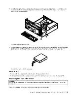
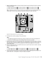
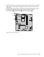


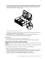


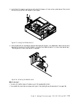


11. Install the new system board into the chassis by aligning the six screw holes in the new system
board with the corresponding mounting studs on the chassis. Then, install the six screws to secure
the system board.
12. Install the heat sink and fan assembly and connect the heat-sink-and-fan-assembly cable to the new
system board. See “Replacing the heat sink and fan assembly” on page 158.
Note:
If necessary, apply the appropriate amount of thermal grease on the bottom of the heat sink
and fan assembly.
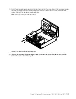
13. Install all memory modules and PCI Express cards removed from the failing system board onto the new
system board. See “Installing or replacing a memory module” on page 141 and “Installing or replacing a
PCI Express card” on page 139.
14. Refer to your record to connect cables to the new system board. You also can refer to “Locating
parts on the system board” on page 80 to help you locate the connectors on the system board and
connect cables.
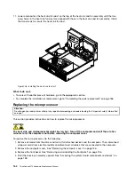
15. To complete the replacement, go to “Completing the parts replacement” on page 186.
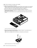
The failing system board must be returned with a microprocessor socket cover to protect the pins during
shipping and handling.
To install the microprocessor socket cover, do the following:
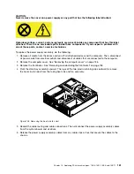
1. After you have removed the microprocessor from the failing system board, close the microprocessor
retainer and then put the lever to the locked position to secure the retainer in place.
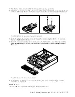
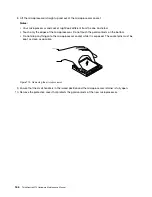
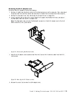
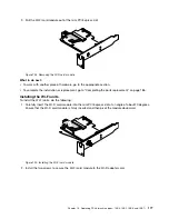
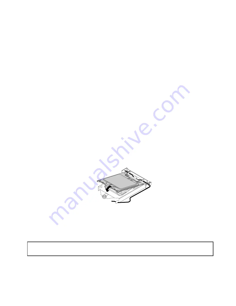
2. Note the orientation of the socket cover, and install one side of the socket cover onto the microprocessor
socket. Carefully press the other side of the socket cover downward until the socket cover snaps
into position.
Note:
Your microprocessor socket and cover might look slightly different from the illustration.
Figure 113. Installing the socket cover onto the microprocessor socket
3. Carefully check the four corners of the socket cover to ensure that the cover is seated securely.
4. Follow any additional instructions included with the replacement part you received.
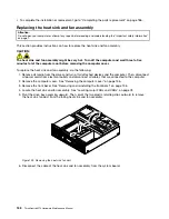
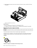
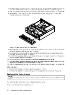
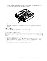
Replacing the front fan assembly
Attention:
Do not open your computer or attempt any repair before reading and understanding the “Important safety information”
on page 1.
This section provides instructions on how to replace the front fan assembly.
To replace the front fan assembly, do the following:
Chapter 10
.
Replacing FRUs (machine types: 10B4, 10B5, 10B6, and 10B7)
169
Summary of Contents for 10AX
Page 6: ...iv ThinkCentre M73 Hardware Maintenance Manual ...
Page 8: ...2 ThinkCentre M73 Hardware Maintenance Manual ...
Page 15: ...Chapter 2 Safety information 9 ...
Page 19: ...Chapter 2 Safety information 13 ...
Page 20: ...1 2 14 ThinkCentre M73 Hardware Maintenance Manual ...
Page 21: ...1 2 Chapter 2 Safety information 15 ...
Page 26: ...1 2 20 ThinkCentre M73 Hardware Maintenance Manual ...
Page 27: ...1 2 Chapter 2 Safety information 21 ...
Page 30: ...24 ThinkCentre M73 Hardware Maintenance Manual ...
Page 34: ...28 ThinkCentre M73 Hardware Maintenance Manual ...
Page 40: ...34 ThinkCentre M73 Hardware Maintenance Manual ...
Page 74: ...68 ThinkCentre M73 Hardware Maintenance Manual ...
Page 92: ...86 ThinkCentre M73 Hardware Maintenance Manual ...
Page 140: ...134 ThinkCentre M73 Hardware Maintenance Manual ...
Page 194: ...188 ThinkCentre M73 Hardware Maintenance Manual ...
Page 248: ...242 ThinkCentre M73 Hardware Maintenance Manual ...
Page 258: ...252 ThinkCentre M73 Hardware Maintenance Manual ...
Page 259: ......
Page 260: ......


