background image

Lenovo 10w 
Hardware Maintenance Manual

Summary of Contents for 10w

Page 1: ...Lenovo 10w Hardware Maintenance Manual ...

Page 2: ...Lenovo 2022 LIMITED AND RESTRICTED RIGHTS NOTICE If data or software is delivered pursuant to a General Services Administration GSA contract use reproduction or disclosure is subject to restrictions set forth in Contract No GS 35F 05925 ...

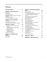
Page 3: ...ervice tool kit 33 Screw notices 33 Chapter 5 Removing or replacing a FRU 35 General guidelines 35 Before servicing the computer 35 Disable Fast Startup and the built in battery 35 1010 Lenovo Integrated Pen for selected models 36 1020 Pen dummy for selected models 36 1030 LCD unit and LCD cable 36 1040 I O board cable 38 1050 Built in battery 39 1060 Charger cable bracket 40 1070 I O board bracke...

Page 4: ...ii Lenovo 10w Hardware Maintenance Manual ...

Page 5: ...trained service technicians who are familiar with products Use this manual along with the advanced diagnostic tests to troubleshoot problems effectively Depending on the model some hardware configuration and software programs might not be available on the computer Some statements in this manual might not be applicable to the computer Before servicing a product be sure to read all the information u...

Page 6: ...iv Lenovo 10w Hardware Maintenance Manual ...

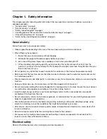
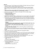
Page 7: ...ians and the customer s personnel are not in a hazardous position Place removed covers and other parts in a safe place away from all personnel while you are servicing the machine Keep your tool case away from walk areas so that other people will not trip over it Do not wear loose clothing that can be trapped in the moving parts of a machine Ensure that your sleeves are fastened or rolled up above ...

Page 8: ...ur back CAUTION An electrical shock can occur only when there is a complete circuit By observing the above rule you may prevent a current from passing through your body When using testers set the controls correctly and use the approved probe leads and accessories for that tester Stand on suitable rubber mats obtained locally if necessary to insulate you from grounds such as metal floor strips and ...

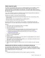
Page 9: ... Disconnect the power cord 3 Check the power cord for a A third wire ground connector in good condition Use a meter to measure third wire ground continuity for 0 1 ohm or less between the external ground pin and the frame ground b The power cord should be the authorized type specified for your computer Go to https support lenovo com partslookup c Insulation must not be frayed or worn 4 Check for c...

Page 10: ...requirement Note The use of a grounding system to guard against ESD damage is desirable but not necessary Attach the ESD ground clip to any frame ground ground braid or green wire ground When working on a double insulated or battery operated system use an ESD common ground or reference point You can use coax or connector outside shells on these systems Use the round ground prong of the ac plug on ...

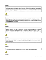
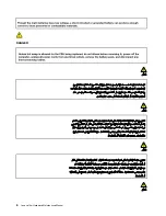
Page 11: ...DANGER DANGER DANGER DANGER DANGER DANGER Chapter 1 Safety information 5 ...

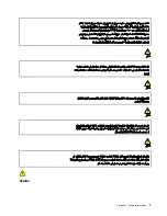
Page 12: ...DANGER 6 Lenovo 10w Hardware Maintenance Manual ...

Page 13: ...PERIGO Chapter 1 Safety information 7 ...

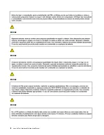
Page 14: ...PERIGO PERIGO PERIGO PERIGO 8 Lenovo 10w Hardware Maintenance Manual ...

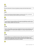
Page 15: ...PERIGO PERIGO PERIGO DANGER DANGER Chapter 1 Safety information 9 ...

Page 16: ...DANGER DANGER DANGER DANGER DANGER 10 Lenovo 10w Hardware Maintenance Manual ...

Page 17: ...DANGER VORSICHT VORSICHT VORSICHT VORSICHT Chapter 1 Safety information 11 ...

Page 18: ...VORSICHT VORSICHT VORSICHT VORSICHT 12 Lenovo 10w Hardware Maintenance Manual ...

Page 19: ...Chapter 1 Safety information 13 ...

Page 20: ...14 Lenovo 10w Hardware Maintenance Manual ...

Page 21: ...Chapter 1 Safety information 15 ...

Page 22: ...16 Lenovo 10w Hardware Maintenance Manual ...

Page 23: ...Chapter 1 Safety information 17 ...

Page 24: ...18 Lenovo 10w Hardware Maintenance Manual ...

Page 25: ...Chapter 1 Safety information 19 ...

Page 26: ...20 Lenovo 10w Hardware Maintenance Manual ...

Page 27: ...RU What to do first When you return a FRU you must include the following information in the parts exchange form or parts return form that you attach to it 1 Name and phone number of service technician 2 Date of service 3 Date on which the machine failed 4 Date of purchase 5 Failure symptoms error codes appearing on the display and beep symptoms 6 Procedure index and page number in which the failin...

Page 28: ...pter 1 Connect the computer to a power outlet and turn on the computer 2 Start the Vantage app and locate the Power section The ac power adapter information is displayed Ensure that you use the ac power adapter that is shipped with the computer to provide enough power to the computer Otherwise a message will be displayed prompting you that the computer will not be charged or will be charged slowly...

Page 29: ...3 Check the battery status again If the same error still exists replace the system board Chapter 2 General checkout 23 ...

Page 30: ...24 Lenovo 10w Hardware Maintenance Manual ...

Page 31: ...nectors Overview Lenovo Integrated Pen Microphone Camera Webcam privacy shutter Touch screen Power button Volume button Audio connector Power connector USB C 3 2 connector Gen 1 Speakers Pogo interface connector for selected models Copyright Lenovo 2022 25 ...

Page 32: ...orm your tablet into a portable notebook computer Overview Pogo pin with guide pin Touchpad Attach your computer to the keyboard Align the keyboard guide pins with the tablet guide pin connectors in the direction shown by the arrows When the keyboard gets close enough it magnetically attaches to your tablet Then you can adjust the tablet to your prefer viewing angle within 180 degrees 26 Lenovo 10...

Page 33: ...To detach your computer you can easily remove the keyboard by pulling it away Chapter 3 Locations 27 ...

Page 34: ...e found at https support lenovo com Click Documentation and then follow the on screen instructions to find the manual for your product You might be required to return the defective CRU When return is required 1 return instructions a prepaid shipping label and a container will be included with the replacement CRU and 2 you might be charged for the replacement CRU if Lenovo does not receive the defe...

Page 35: ...Major FRUs and CRUs Chapter 3 Locations 29 ...

Page 36: ... board No No 15 Rear LED rubber No No 16 Microphone rubbers No No 17 Front camera with cable No No 18 Wireless LAN antennas No No 19 Microphone board cable No No 20 Rear camera No No 21 Rear camera bracket No No 22 Pen charger cable No No 23 LCD cable No No 24 Lenovo Integrated Pen Yes No 25 Pen dummy Yes No a Lenovo factory recovery USB key No No b Power cord Yes No c Miscellaneous parts kits see...

Page 37: ... shipping and handling fees might apply Miscellaneous parts Table 2 Miscellaneous part FRU descriptions Self service CRU Optional service CRU Screw kit M1 2 x L2 black 2 M1 6 x L1 7 silver 4 M1 6 x L2 3 black 25 M1 6 x L3 5 black 6 No No Looking up FRU information For detailed FRU information including part numbers descriptions and substitution part numbers go to https support lenovo com partslook...

Page 38: ...32 Lenovo 10w Hardware Maintenance Manual ...

Page 39: ...e tool Notes Specifications of the Phillips head screwdriver 2 Screwdriver head diameter φ2 0 mm Screwdriver head length 15 mm The silicone grease can be applied to the surfaces of the microprocessor and heatsink to eliminate air gaps Screw notices Loose screws can cause a reliability problem In your computer this problem is addressed with special nylon coated screws that have the following charac...

Page 40: ...uches the surface of the logic card Notes Ensure that you use the correct screw It is recommended to use new screws for replacements If you have a torque screwdriver tighten all screws firmly to the torque specified in the screw information table for each step Ensure torque screwdrivers are calibrated correctly following country specifications 34 Lenovo 10w Hardware Maintenance Manual ...

Page 41: ...rrect screws as shown in the replacement procedures DANGER Before removing any FRU turn off the computer unplug all power cords from electrical outlets disable the built in battery and then disconnect any interconnecting cables Attention After replacing a FRU do not turn on the computer until you have made sure that all screws springs and other small parts are in place and none are loose inside th...

Page 42: ... minutes to let the computer cool 1010 Lenovo Integrated Pen for selected models Depending on models your tablet might come with a Lenovo Integrated Pen Removal steps of the Lenovo Integrated Pen 1020 Pen dummy for selected models Depending on models your tablet might come with a pen dummy Removal steps of the pen dummy 1030 LCD unit and LCD cable For access remove these FRUs in order 1010 Lenovo ...

Page 43: ...Step Screw quantity Color Torque 1 M1 2 2 0 mm flat head nylon coated 2 Black 0 039 0 015 Nm 0 4 0 05 kgf cm Note Loose the screws in step 1 with Phillips head screwdriver 2 see Service tool kit on page 33 Chapter 5 Removing or replacing a FRU 37 ...

Page 44: ...hed firmly 1040 I O board cable For access remove these FRUs in order 1010 Lenovo Integrated Pen for selected models on page 36 1020 Pen dummy for selected models on page 36 1030 LCD unit and LCD cable on page 36 38 Lenovo 10w Hardware Maintenance Manual ...

Page 45: ...y FRU should not be replaced unless this diagnostic test shows that the battery is defective The only exception to this is if the built in battery is physically damaged or a customer is reporting a possible safety issue If the Vantage app is not installed on the computer the customer should download and install the program to diagnose the built in battery before getting a non physically damaged bu...

Page 46: ...cess remove these FRUs in order 1010 Lenovo Integrated Pen for selected models on page 36 1020 Pen dummy for selected models on page 36 1030 LCD unit and LCD cable on page 36 Removal steps of the charger cable bracket Step Screw quantity Color Torque 1 M1 6 2 3 mm flat head nylon coated 4 Black 0 1 0 015 Nm 1 1 0 05 kgf cm 2 M1 6 3 5 mm flat head nylon coated 2 Black 0 1 0 015 Nm 1 1 0 05 kgf cm 4...

Page 47: ...mm flat head nylon coated 4 Black 0 1 0 015 Nm 1 1 0 05 kgf cm 1080 Rear camera and rear camera bracket For access remove these FRUs in order 1010 Lenovo Integrated Pen for selected models on page 36 1020 Pen dummy for selected models on page 36 1030 LCD unit and LCD cable on page 36 Removal steps of the rear camera and rear camera bracket Step Screw quantity Color Torque 1 M1 6 2 3 mm flat head n...

Page 48: ...odels on page 36 1030 LCD unit and LCD cable on page 36 Removal steps of the pen charger cable Step Screw quantity Color Torque 2 M1 6 2 3 mm flat head nylon coated 1 Black 0 1 0 015 Nm 1 1 0 05 kgf cm When installing Ensure that the connector is attached firmly Ensure that the cable is routed properly 1100 Microphone board cable For access remove these FRUs in order 42 Lenovo 10w Hardware Mainten...

Page 49: ...ing Ensure that the connectors are attached firmly 1110 I O board and function board cable For access remove these FRUs in order 1010 Lenovo Integrated Pen for selected models on page 36 1020 Pen dummy for selected models on page 36 1030 LCD unit and LCD cable on page 36 1070 I O board bracket on page 41 Removal steps of the I O board and function board cable Chapter 5 Removing or replacing a FRU ...

Page 50: ...ttery on page 39 1060 Charger cable bracket on page 40 Removal steps of the pogo pin cable When installing Ensure that the connector is attached firmly 1130 Speaker assembly For access remove these FRUs in order 1010 Lenovo Integrated Pen for selected models on page 36 1020 Pen dummy for selected models on page 36 1030 LCD unit and LCD cable on page 36 1040 I O board cable on page 38 1070 I O boar...

Page 51: ...th cable For access remove these FRUs in order 1010 Lenovo Integrated Pen for selected models on page 36 1020 Pen dummy for selected models on page 36 1030 LCD unit and LCD cable on page 36 1100 Microphone board cable on page 42 Removal steps of the front camera with cable When installing Ensure that the connector is attached firmly 1150 Microphone board microphone rubber and rear LED rubber For a...

Page 52: ...p Screw quantity Color Torque 1 M1 6 1 5 mm flat head nylon coated 2 Silver 0 1 0 015 Nm 1 1 0 05 kgf cm 1160 Wireless LAN antennas For access remove these FRUs in order 1010 Lenovo Integrated Pen for selected models on page 36 1020 Pen dummy for selected models on page 36 1030 LCD unit and LCD cable on page 36 1100 Microphone board cable on page 42 1140 Front camera with cable on page 45 1150 Mic...

Page 53: ...30 LCD unit and LCD cable on page 36 1100 Microphone board cable on page 42 1140 Front camera with cable on page 45 1150 Microphone board microphone rubber and rear LED rubber on page 45 1160 Wireless LAN antennas on page 46 Removal steps of the heatsink Step Screw quantity Color Torque 1 M1 6 2 3 mm flat head nylon coated 8 Black 0 1 0 015 Nm 1 1 0 05 kgf cm Chapter 5 Removing or replacing a FRU ...

Page 54: ...uch as metal wood or composite Avoid rough handling of any kind At every point in the process be sure not to drop or stack the system board If you put a system board down be sure to put it only on a padded surface such as an ESD mat or a corrugated conductive surface Avoid bending a system board and hard pushing to prevent cracking at each BGA Ball Grid Array chipset For access remove these FRUs i...

Page 55: ...r cable bracket on page 40 1070 I O board bracket on page 41 1080 Rear camera and rear camera bracket on page 41 1090 Pen charger cable on page 42 1100 Microphone board cable on page 42 1110 I O board and function board cable on page 43 1120 Pogo pin cable on page 44 1130 Speaker assembly on page 44 1140 Front camera with cable on page 45 1150 Microphone board microphone rubber and rear LED rubber...

Page 56: ...ning labels of several kinds Apply those labels when you replace the base cover assembly For the labels that are not shipped with the new base cover assembly peel them from the old base cover assembly and adhere them to the new one 1 Country label 2 Rating label 3 S N label 4 TCO label 5 CO2 Offset Service by Lenovo label 6 GML label 7 QR code label 50 Lenovo 10w Hardware Maintenance Manual ...

Page 57: ...ublication Lenovo may make improvements and or changes in the product s and or the program s described in this publication at any time without notice The products described in this document are not intended for use in implantation or other life support applications where malfunction may result in injury or death to persons The information contained in this document does not affect or change Lenovo...

Page 58: ...trademark of the Microsoft group of companies USB C is a registered trademark of USB Implementers Forum Wi Fi and Miracast are registered trademarks of Wi Fi Alliance All other trademarks are the property of their respective owners 52 Lenovo 10w Hardware Maintenance Manual ...

Page 59: ...aceable Unit CTO Configure To Order EAIA Enhanced Asset Information Area EEPROM Electrically Erasable Programmable Read Only Memory EFI Extensible Firmware Interface ESD Electrostatic discharge FRU Field Replaceable Unit GAV General Announce Variant IC Integrated circuits LCD Liquid Crystal Display MTM Machine type and model POST Power on self test RFID Radio frequency identification SVP Superviso...

Page 60: ...54 Lenovo 10w Hardware Maintenance Manual ...

Page 61: ......

Page 62: ...Part Number XXXX Printed in China 1P P N XXXX 1PXXXX ...

Reviews: