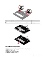
• “1060 Memory module” on page 71
• “1070 Speaker assembly” on page 71
• “1080 Built-in battery” on page 72
• “1090 Thermal fan assembly” on page 73
• “1110 Always On USB 3.2 connector Gen 1 cable, bracket and board” on page 74
• “1120 Ethernet card cable, bracket and board” on page 75
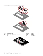
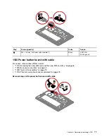
• “1130 Power button board with cable” on page 77
• “1140 Smart card reader module and cable (for selected models)” on page 78
• “1150 Fingerprint reader cable, bracket and board” on page 79
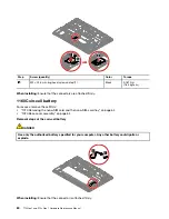
• “1160 Coin-cell battery” on page 80
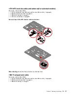
• “1170 NFC module, cable and antenna (for selected models)” on page 81
• “1180 Trackpad and cable” on page 81
• “1190 Hall sensor board with cable” on page 82
• “1210 System board ” on page 83
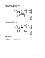
• “1220 LCD unit” on page 87
Removing an LCD FRU
This section provides instructions on how to remove an LCD FRU.
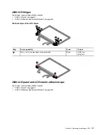
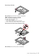
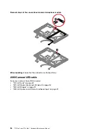
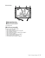
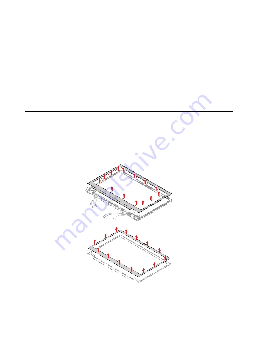
2010 LCD bezel sheet and LCD bezel
For access, remove this FRU:
• “1220 LCD unit” on page 87
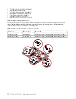
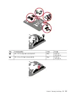
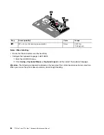
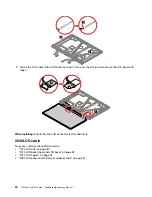
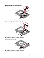
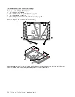
Removal steps of the LCD bezel sheet and LCD bezel
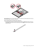
When installing:
After the LCD bezel sheet is removed, it cannot be used anymore. A new LCD bezel sheet
is required for replacement.
90
T15 Gen 1 and P15s Gen 1 Hardware Maintenance Manual
Summary of Contents for 20S7S02U00
Page 1: ...T15 Gen 1 and P15s Gen 1 Hardware Maintenance Manual ...
Page 6: ...iv T15 Gen 1 and P15s Gen 1 Hardware Maintenance Manual ...
Page 11: ...DANGER DANGER DANGER DANGER DANGER Chapter 1 Safety information 5 ...
Page 12: ...6 T15 Gen 1 and P15s Gen 1 Hardware Maintenance Manual ...
Page 13: ...PERIGO PERIGO Chapter 1 Safety information 7 ...
Page 14: ...PERIGO PERIGO PERIGO PERIGO PERIGO 8 T15 Gen 1 and P15s Gen 1 Hardware Maintenance Manual ...
Page 15: ...PERIGO DANGER DANGER DANGER DANGER Chapter 1 Safety information 9 ...
Page 16: ...DANGER DANGER DANGER DANGER VORSICHT 10 T15 Gen 1 and P15s Gen 1 Hardware Maintenance Manual ...
Page 17: ...VORSICHT VORSICHT VORSICHT VORSICHT Chapter 1 Safety information 11 ...
Page 18: ...VORSICHT VORSICHT VORSICHT 12 T15 Gen 1 and P15s Gen 1 Hardware Maintenance Manual ...
Page 19: ...Chapter 1 Safety information 13 ...
Page 20: ...14 T15 Gen 1 and P15s Gen 1 Hardware Maintenance Manual ...
Page 21: ...Chapter 1 Safety information 15 ...
Page 22: ...16 T15 Gen 1 and P15s Gen 1 Hardware Maintenance Manual ...
Page 23: ...Chapter 1 Safety information 17 ...
Page 24: ...18 T15 Gen 1 and P15s Gen 1 Hardware Maintenance Manual ...
Page 25: ...Chapter 1 Safety information 19 ...
Page 26: ...20 T15 Gen 1 and P15s Gen 1 Hardware Maintenance Manual ...
Page 30: ...24 T15 Gen 1 and P15s Gen 1 Hardware Maintenance Manual ...
Page 50: ...44 T15 Gen 1 and P15s Gen 1 Hardware Maintenance Manual ...
Page 73: ...a b c d Chapter 8 Removing or replacing a FRU 67 ...
Page 106: ...100 T15 Gen 1 and P15s Gen 1 Hardware Maintenance Manual ...
Page 109: ......
Page 110: ...Part Number SP40W87587 Printed in 1P P N SP40W87587 ...
Page 111: ... 1PSP40W87587 ...

