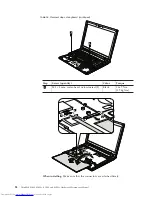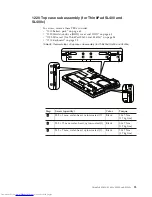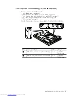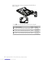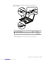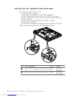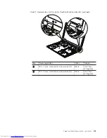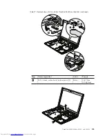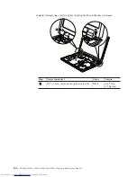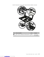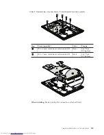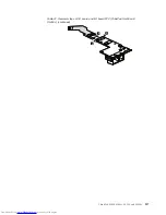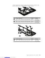
Table
38.
Removal
steps
of
LCD
unit
(for
ThinkPad
SL500
and
SL500c)
(continued)
7
8
8
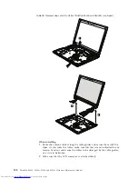
When
installing:
1.
Route
the
antenna
cables
along
the
cable
guides
and
secure
them
with
the
tapes.
As
you
route
the
cables,
make
sure
that
they
are
not
subjected
to
any
tension.
Tension
could
cause
the
cables
to
be
damaged
by
the
cable
guides,
or
a
wire
to
be
broken.
2.
Make
sure
that
the
LCD
connector
is
attached
firmly.
108
ThinkPad
SL400,
SL400c,
SL500,
and
SL500c
Hardware
Maintenance
Manual
Summary of Contents for 27434AU
Page 1: ...ThinkPad SL400 SL400c SL500 and SL500c Hardware Maintenance Manual ...
Page 2: ......
Page 3: ...ThinkPad SL400 SL400c SL500 and SL500c Hardware Maintenance Manual ...
Page 8: ...vi ThinkPad SL400 SL400c SL500 and SL500c Hardware Maintenance Manual ...
Page 24: ...16 ThinkPad SL400 SL400c SL500 and SL500c Hardware Maintenance Manual ...
Page 30: ...22 ThinkPad SL400 SL400c SL500 and SL500c Hardware Maintenance Manual ...
Page 40: ...32 ThinkPad SL400 SL400c SL500 and SL500c Hardware Maintenance Manual ...
Page 56: ...48 ThinkPad SL400 SL400c SL500 and SL500c Hardware Maintenance Manual ...
Page 211: ...15 4 in WXGA TFT 3 4 5 6 7 8 9 2 1 ThinkPad SL400 SL400c SL500 and SL500c 203 ...
Page 239: ......

