background image

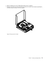
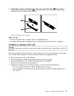
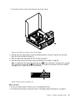
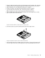
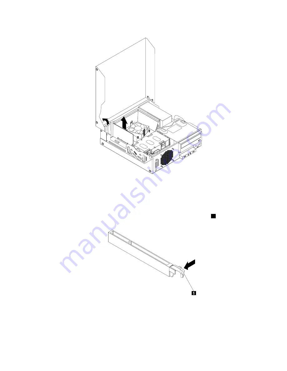
Figure 15. Removing a PCI card

Notes:

a. The card fits tightly into the card slot. If necessary, alternate moving each side of the card a small

amount until it is removed from the card slot.

b. If the card is held in place by a retaining latch, press the card retaining latch

1

as shown to

disengage the latch. Grasp the card and gently pull it out of the slot.

5. Remove the new PCI card from its static-protective package.

38

ThinkCentre User Guide

Summary of Contents for 2934, 2941, 2945, 2961,2982, 2988, 2993, 2996, 3181, 3183, 3185, 3187, 3198, 3202, 3207,ThinkCentre 3209

Page 1: ...ThinkCentre User Guide Machine Types 2756 2800 2929 2932 2934 2941 2945 2961 2982 2988 2993 2996 3181 3183 3185 3187 3198 3202 3207 3209 3214 3218 3224 3227 3306 3393 and 3395 ...

Page 2: ...tion on page v and Appendix A Notices on page 129 Second Edition September 2012 Copyright Lenovo 2012 LIMITED AND RESTRICTED RIGHTS NOTICE If data or software is delivered pursuant a General Services Administration GSA contract use reproduction or disclosure is subject to restrictions set forth in Contract No GS 35F 05925 ...

Page 3: ...Setting the volume from Control Panel 20 Using CDs and DVDs 20 Handling and storing CD and DVD media 20 Playing a CD or DVD 21 Recording a CD or DVD 21 Chapter 3 You and your computer 23 Accessibility and comfort 23 Arranging your workspace 23 Comfort 23 Glare and lighting 24 Air circulation 24 Electrical outlets and cable lengths 24 Registering your computer 25 Moving your computer to another cou...

Page 4: ... compliance mode 98 ICE performance mode 99 ICE thermal alert 99 Exiting the Setup Utility program 100 Chapter 8 Updating system programs 101 Using system programs 101 Updating flashing the BIOS from a disc 101 Updating flashing the BIOS from your operating system 102 Recovering from a POST BIOS update failure 102 Chapter 9 Preventing problems 103 Keeping your computer current 103 Getting the late...

Page 5: ...endix C WEEE and recycling information 135 Important WEEE information 135 Recycling information 135 Recycling information for Brazil 136 Battery recycling information for Taiwan 136 Battery recycling information for the European Union 137 Appendix D Restriction of Hazardous Substances Directive RoHS 139 China RoHS 139 Turkish RoHS 139 Ukraine RoHS 139 India RoHS 140 Appendix E ENERGY STAR model in...

Page 6: ...iv ThinkCentre User Guide ...

Page 7: ...on are referred to as Customer Replaceable Units or CRUs Lenovo provides documentation with instructions when it is appropriate for customers to install options or replace CRUs You must closely follow all instructions when installing or replacing parts The Off state of a power indicator does not necessarily mean that voltage levels inside a product are zero Before you remove the covers from a prod...

Page 8: ...ng so can stress the cord in ways that can cause the cord to fray crack or crimp This can present a safety hazard Always route power cords so that they will not be walked on tripped over or pinched by objects Protect power cord and power adapters from liquids For instance do not leave your power cord or power adapter near sinks tubs toilets or on floors that are cleaned with liquid cleansers Liqui...

Page 9: ... you might damage your computer To avoid possible damage to attached devices wait at least five seconds after the computer is shut down to disconnect external devices Heat and product ventilation Computers power adapters and many accessories can generate heat when turned on and when batteries are charging Always follow these basic precautions Do not leave your computer power adapter or accessories...

Page 10: ...sunshine Keep electrical appliances such as an electric fan radio high powered speakers air conditioner and microwave oven away from your computer because the strong magnetic fields generated by these appliances can damage the monitor and data on the hard disk drive Do not place any beverages on top of or beside the computer or other attached devices If liquid is spilled on or in the computer or a...

Page 11: ... not view directly with optical instruments and avoid direct exposure to the beam Power supply statement Never remove the cover on a power supply or any part that has the following label attached Hazardous voltage current and energy levels are present inside any component that has this label attached There are no serviceable parts inside these components If you suspect a problem with one of these ...

Page 12: ...x ThinkCentre User Guide ...

Page 13: ...isplay the charms Then click Settings PC info to view the information Microprocessor Your computer comes with one of the following microprocessors internal cache size varies by model type Intel Core i3 microprocessor Intel Core i5 microprocessor Intel Core i7 microprocessor Intel Celeron microprocessor Intel Pentium microprocessor Memory Your computer supports up to four double data rate 3 unbuffe...

Page 14: ...ters using a network interface independent of data storage devices such as the hard disk drive or installed operating systems Intelligent Cooling Engine ICE The Intelligent Cooling Engine is a system thermal management solution that enables your computer to run with better thermal and acoustic performance The ICE function also monitors the thermal performance of your computer to identify thermal p...

Page 15: ...x1 card slot One PCI Express x16 graphics card slot Two PCI card slots Power supply Your computer comes with a 240 watt automatic voltage sensing power supply Security features Computrace Agent software embedded in firmware Cover presence switch also called intrusion switch Ability to enable or disable a device Ability to enable and disable USB connectors individually Keyboard with fingerprint rea...

Page 16: ... to 60 C 14 F to 140 F without package Humidity Operating 20 to 80 non condensing Storage 20 to 90 non condensing Altitude Operating 50 to 10 000 ft 15 2 to 3048 m Storage 50 to 35 000 ft 15 2 to 10 668 m Electrical input Input voltage Low range Minimum 100 V ac Maximum 127 V ac Input frequency range 50 to 60 Hz High range Minimum 200 V ac Maximum 240 V ac Input frequency range 50 to 60 Hz 1 The o...

Page 17: ...am Program Icon name Communications Utility Web Conferencing Fingerprint Software Fingerprint Reader Lenovo Solution Center System Health and Diagnostics Password Manager Password Vault Power Manager Power Controls Recovery Media Factory Recovery Disks Rescue and Recovery Enhanced Backup and Restore SimpleTap SimpleTap System Update Update and Drivers View Management Utility Screen Layout Note Dep...

Page 18: ...be available Accessing Lenovo programs on the Windows 8 operating system If your computer is preinstalled with the Windows 8 operating system you can access Lenovo programs by doing either of the following Click the Lenovo Start icon from the taskbar A list of programs is displayed Double click a Lenovo program to launch it If a desired program is not in the list click the plus icon Press the Wind...

Page 19: ...optimizing your power plan settings and creating and managing multiple network profiles Lenovo Solution Center The Lenovo Solution Center program enables you to troubleshoot and resolve computer problems It combines diagnostic tests system information collection security status and support information along with hints and tips for maximum system performance Lenovo Start The Lenovo Start program pr...

Page 20: ...top after you have launched the SimpleTap program for the first time Press the blue ThinkVantage button if your keyboard has one Note The SimpleTap program is only available on certain models preinstalled with the Windows 7 operating system If your Windows 7 model is not preinstalled with the SimpleTap program you can download it from http www lenovo com support System Update The System Update pro...

Page 21: ...the connectors controls and indicators on the front of your computer Figure 1 Front connector control and indicator locations 1 Optical drive eject close button 5 USB 2 0 connector USB port 2 2 Power switch 6 Microphone connector 3 Hard disk drive activity indicator 7 Headphone connector 4 Power indicator 8 USB 2 0 connector USB port 1 Chapter 1 Product overview 9 ...

Page 22: ...ors USB ports 3 and 4 15 Ethernet connector 7 Microphone connector 16 Integrated cable lock Kingston lock slot 8 Audio line out connector 17 Cover release button 9 Audio line in connector 18 PS 2 keyboard and mouse connectors optional Connector Description Audio line in connector Used to receive audio signals from an external audio device such as a stereo system When you attach an external audio d...

Page 23: ...eyboard that uses a PS 2 keyboard connector PS 2 mouse connector optional Used to attach a mouse a trackball or other pointing devices that use a PS 2 mouse connector USB 2 0 connector Used to attach a device that requires a USB 2 0 connector such as a USB keyboard a USB mouse a USB scanner or a USB printer If you have more than eight USB devices you can purchase a USB hub which you can use to con...

Page 24: ...ystem fan assembly 2 Power supply assembly 8 Internal speaker installed in some models 3 Memory module 9 Cover presence switch Intrusion switch installed in some models 4 Optical drive 10 Hard disk drive or solid state drive 5 Front audio and USB assembly 11 PCI card installed in some models 6 Front bezel 12 Heat sink fan duct Locating parts on the system board Note Your computer comes with one of...

Page 25: ...t 2 DIMM 2 20 Front USB connector 2 for connecting an additional USB device 6 Memory slot 3 DIMM 3 21 Serial COM2 connector 7 Memory slot 4 DIMM 4 22 Internal speaker connector 8 Thermal sensor connector 23 Front audio connector 9 4 pin SATA power connectors 2 24 PCI card slots 2 10 14 pin power connector 25 DisplayPort connector 11 SATA connectors 1 and 2 SATA 3 0 connectors 26 PCI Express x1 car...

Page 26: ...ry slot 2 DIMM 2 20 Front USB connector 2 for connecting additional USB devices 6 Memory slot 3 DIMM 3 21 Serial COM2 connector 7 Memory slot 4 DIMM 4 22 Internal speaker connector 8 Thermal sensor connector 23 Front audio connector 9 4 pin SATA power connectors 2 24 PCI card slots 2 10 14 pin power connector 25 DisplayPort connector 11 SATA connector 1 SATA 3 0 connector 26 PCI Express x1 card sl...

Page 27: ...ng an internal drive it is important to note the type and size of the drive that you can install or replace in each bay and correctly connect the cables to the drive installed Refer to the appropriate section in Chapter 5 Installing or replacing hardware on page 31 for instructions on how to install or replace internal drives for your computer Figure 6 Drive bay locations on page 15 shows the loca...

Page 28: ...puter When you contact Lenovo for help the machine type and model information helps support technicians to identify your computer and provide faster service The following is a sample of the machine type and model label Figure 7 Machine type and model label 16 ThinkCentre User Guide ...

Page 29: ...ry process During the recovery process you might be prompted to change discs Where can I find help about the Windows operating system The Windows Help and Support information system provides you with detailed information about using the Windows operating system to help you get the most of your computer To access the Windows Help and Support information system do one of the following On the Windows...

Page 30: ...ated next to the Ctrl key on the right side of the Spacebar Pressing the context menu key opens the context menu for the active program icon or object Note You can use the mouse or the Up and Down arrow keys to highlight menu selections On the Windows 7 operating system you can close the Start menu or the context menu by clicking the mouse or pressing Esc Using the blue ThinkVantage button Some ke...

Page 31: ...e the connectors provided on the audio adapter Each audio solution provides at least three audio connectors audio line in connector audio line out connector and Microphone connector On some models a fourth connector is provided for the attachment of unpowered stereo speakers speakers that do not require an ac power source The audio adapter provides you with the ability to record and play back soun...

Page 32: ...OM drive or recordable DVD drive installed DVD drives use industry standard 12 cm 4 75 inch CD media or DVD media If your computer comes with a DVD drive the drive can read DVD ROM discs DVD R discs DVD RAM discs DVD RW discs and all types of CDs such as CD ROM discs CD RW discs CD R discs and audio CDs If you have a recordable DVD drive it can also record on DVD R discs DVD RW discs type II DVD R...

Page 33: ...the tray forward Note If the tray does not slide out of the drive when you press the Eject Load button insert a straightened paper clip into the emergency eject hole located on the front of the DVD drive Ensure that the drive is powered off when using the emergency eject Use the Eject Load button instead of the emergency eject except in an emergency Recording a CD or DVD If your computer comes wit...

Page 34: ...22 ThinkCentre User Guide ...

Page 35: ...in your operating system others can be purchased through vendors or accessed through the World Wide Web http www lenovo com healthycomputing Arranging your workspace To get the most from your computer arrange both the equipment you use and your work area to suit your needs and the kind of work you do Your comfort is of foremost importance but light sources air circulation and the location of elect...

Page 36: ...clarity of the image on the screen try them only after you have exhausted other methods of reducing glare Dust buildup compounds problems associated with glare Remember to clean your monitor screen periodically using a soft cloth as directed in your monitor documentation Air circulation Your computer and monitor produce heat The computer has a fan that pulls in fresh air and forces out hot air The...

Page 37: ...elocate your computer to another country or region you must be certain that you have matched your computer to the voltage available at your electrical outlet CAUTION You must know the voltage of the electrical connection outlet where your computer will be connected If you do not know the voltage contact your local electric company or refer to official Web sites or other literature for travelers to...

Page 38: ...al outlet style different from the type you are currently using you will have to purchase either electrical plug adapters or new power cords You can order power cords directly from Lenovo For power cord information and part numbers go to http www lenovo com powercordnotice 26 ThinkCentre User Guide ...

Page 39: ...you turn on the computer an error message will be displayed To bypass the error message and log in to the operating system do the following 1 Properly install or close your computer cover See Completing the parts replacement on page 85 2 Press F1 to enter the Setup Utility program Then press F10 to save and exit the Setup Utility program The error message will not be displayed again Ability to ena...

Page 40: ...oft Windows operating system and through the BIOS of your computer to help deter unauthorized use of your computer BIOS passwords You can use the BIOS Setup Utility program to set passwords to prevent unauthorized access to your computer and data The following types of passwords are available Power On Password When a Power On Password is set you are prompted to type a valid password each time the ...

Page 41: ...Utility program main menu select Security Fingerprint Setup and press Enter The Fingerprint Setup window opens 3 Select Preboot Authentication or Erase Fingerprint Data as desired and press Enter 4 Select the desired settings and press Enter 5 Press F10 to save changes and exit the Setup Utility program Press Enter when prompted to confirm the exit Using and understanding firewalls A firewall can ...

Page 42: ...For more information about how to use your antivirus software refer to the help system of your antivirus software 30 ThinkCentre User Guide ...

Page 43: ...out setting the part down When this is not possible place the static protective package that the part came in on a smooth level surface and place the part on it Do not place the part on the computer cover or other metal surface Installing or replacing hardware This section provides instructions on how to install or replace hardware for your computer You can expand the capabilities of your computer...

Page 44: ...ur computer on page 9 and Locating connectors on the rear of your computer on page 10 4 Remove any locking device that secures the computer cover such as an integrated cable lock See Attaching an integrated cable lock on page 28 5 Press the cover release button at the rear of the computer and pivot the computer cover upward Figure 9 Opening the computer cover Removing and reinstalling the front be...

Page 45: ...ver on page 32 3 Remove the front bezel by releasing the three plastic tabs on the top of the front bezel and pivoting the front bezel outward to remove it from the computer Figure 10 Removing the front bezel Chapter 5 Installing or replacing hardware 33 ...

Page 46: ...nderstanding the Important safety information on page v This section provides instructions on how to access the system board components and drives To access the system board components and drives do the following 1 Remove all media from the drives and turn off all attached devices and the computer Then disconnect all power cords from electrical outlets and disconnect all cables that are connected ...

Page 47: ...e numbers 1 2 3 and 4 indicate the installation sequence To locate the memory module slots see Locating parts on the system board on page 12 UDIMM DIMM 1 DIMM 2 DIMM 3 DIMM 4 One UDIMM X Two UDIMMs X 1 X 2 Three UDIMMs X 3 X 1 X 2 Four UDIMMs X 3 X 1 X 4 X 2 To install or replace a memory module do the following 1 Turn off the computer and disconnect all power cords from electrical outlets 2 Open ...

Page 48: ...ly pull the memory module out of the memory slot Figure 12 Removing a memory module If you are installing a memory module open the retaining clips of the memory slot into which you want to install the memory module Figure 13 Opening the retaining clips 36 ThinkCentre User Guide ...

Page 49: ...safety information on page v This section provides instructions on how to install or replace a PCI card Your computer has two standard PCI card slots one PCI Express x1 card slot and one PCI Express x16 graphics card slot To install or replace a PCI card do the following 1 Turn off the computer and disconnect all power cords from electrical outlets 2 Open the computer cover See Opening the compute...

Page 50: ... of the card a small amount until it is removed from the card slot b If the card is held in place by a retaining latch press the card retaining latch 1 as shown to disengage the latch Grasp the card and gently pull it out of the slot 5 Remove the new PCI card from its static protective package 38 ThinkCentre User Guide ...

Page 51: ...ides instructions on how to install or replace the card reader Note The card reader is only available in some models For new installation see Installing the card reader on page 39 For replacement see Replacing the card reader on page 42 Installing the card reader To install the card reader do the following 1 Remove all media from the drives and turn off all attached devices and the computer Then d...

Page 52: ...card reader bracket Then install the two screws to secure the card reader to the bracket 6 Install the card reader bracket to the chassis Then push the bracket to the left to align the screw hole in the bracket with the corresponding hole in the chassis Figure 17 Installing the card reader 40 ThinkCentre User Guide ...

Page 53: ...ving and reinstalling the front bezel on page 32 Note You might have to remove the card reader cover 2 from the front bezel To remove the card read cover pivot the two retaining clips 1 that secure the card reader cover outwards and then completely disengage the card reader cover from the front bezel Figure 19 Removing the card reader cover What to do next To work with another piece of hardware go...

Page 54: ...der drive bay See Locating internal drives on page 15 5 Pivot the optical drive bay upward and disconnect the card reader cable from the USB connector on the system board See Locating parts on the system board on page 12 6 Remove the screw that secures the card reader bracket Then remove the card reader bracket from the chassis Figure 20 Removing the screw that secures the card reader 7 Remove the...

Page 55: ...er bracket to the chassis Then push the bracket to the left to align the screw hole in the bracket with the corresponding hole in the chassis Figure 21 Installing the card reader Chapter 5 Installing or replacing hardware 43 ...

Page 56: ...n To complete the installation or replacement go to Completing the parts replacement on page 85 Installing or replacing the mSATA solid state drive Attention Do not open your computer or attempt any repair before reading and understanding the Important safety information on page v This section provides instructions on how to install or replace the mSATA solid state drive Note The mSATA solid state...

Page 57: ...cover of the mSATA solid state drive bay 5 Insert the mSATA solid state drive into the mini PCI Express slot on the storage converter and then press the mSATA solid state drive downward Figure 23 Installing the mSATA solid state drive into the storage converter 6 Install the two screws to secure the mSATA solid state drive to the storage converter Figure 24 Installing the screws that secure the mS...

Page 58: ...Figure 25 Installing the mSATA solid state drive storage converter 8 Install the screw to secure the mSATA solid state drive storage converter to the chassis 46 ThinkCentre User Guide ...

Page 59: ...drives and turn off all attached devices and the computer Then disconnect all power cords from electrical outlets and disconnect all cables that are connected to the computer 2 Open the computer cover See Opening the computer cover on page 32 3 Remove the front bezel See Removing and reinstalling the front bezel on page 32 4 Locate the mSATA solid state drive bay See Locating internal drives on pa...

Page 60: ...ATA solid state drive storage converter 8 Remove the two screws that secure the mSATA solid state drive from the storage converter Figure 28 Removing the screws that secure the mSATA solid state drive 48 ThinkCentre User Guide ...

Page 61: ...id state drive into the mini PCI Express slot on the storage converter and then press the mSATA solid state drive downward Figure 30 Installing the mSATA solid state drive into the storage converter 11 Install the two screws to secure the mSATA solid state drive to the storage converter Figure 31 Installing the screws that secure the mSATA solid state drive Chapter 5 Installing or replacing hardwa...

Page 62: ...age converter into the chassis Then push the converter to the left to align the screw hole in the converter with the corresponding hole in the chassis Figure 32 Installing the mSATA solid state drive storage converter 50 ThinkCentre User Guide ...

Page 63: ...pleting the parts replacement on page 85 Replacing the battery Attention Do not open your computer or attempt any repair before reading and understanding the Important safety information on page v Your computer has a special type of memory that maintains the date time and settings for built in features such as parallel port assignments configuration A battery keeps this information active when you...

Page 64: ...the computer is turned on for the first time after replacing the battery an error message might be displayed This is normal after replacing the battery 7 Turn on the computer and all attached devices 8 Use the Setup Utility program to set the date time and any passwords See Chapter 7 Using the Setup Utility program on page 95 What to do next To work with another piece of hardware go to the appropr...

Page 65: ...dapter into the 3 5 inch hard disk drive bracket flex the bracket and align pin 1 pin 2 pin 3 and pin 4 on the bracket with the corresponding holes in the adapter Figure 37 Installing the solid state disk with the adapter into the hard disk drive bracket 3 Connect the signal cable and the power cable to the solid state disk 4 Install the solid state disk into the hard disk drive bay See Replacing ...

Page 66: ...nch solid state disk To install the solid state disk see Installing the solid state disk on page 52 To replace the hard disk drive do the following 1 Turn off the computer and disconnect all power cords from electrical outlets 2 Open the computer cover See Opening the computer cover on page 32 3 Locate the hard disk drive See Locating components on page 12 4 Pull on the handle of the hard disk dri...

Page 67: ...ew hard disk drive into the bracket flex the bracket and align pin 1 pin 2 pin 4 and pin 5 on the bracket with the corresponding holes in the hard disk drive Important Do not touch the circuit board 3 on the bottom of the hard disk drive 8 Connect the signal cable and the power cable to the new hard disk drive Chapter 5 Installing or replacing hardware 55 ...

Page 68: ...parts replacement on page 85 Replacing the optical drive Attention Do not open your computer or attempt any repair before reading and understanding the Important safety information on page v This section provides instructions on how to replace the optical drive To replace the optical drive do the following 1 Turn off the computer and disconnect all power cords from electrical outlets 2 Open the co...

Page 69: ...aining clip to pivot the optical drive bay upward Figure 41 Pivoting the optical drive bay 6 Disconnect the signal cable and the power cable from the rear of the optical drive Chapter 5 Installing or replacing hardware 57 ...

Page 70: ...e optical drive out of the rear of the drive bay assembly Figure 42 Removing the old optical drive 8 Install the optical drive retainer on the side of the new optical drive Figure 43 Installing the optical drive retainer 58 ThinkCentre User Guide ...

Page 71: ...g and understanding the Important safety information on page v This section provides instructions on how to replace the heat sink and fan assembly CAUTION The heat sink and fan assembly might be very hot Turn off the computer and wait three to five minutes to let the computer cool before removing the computer cover To replace the heat sink and fan assembly do the following 1 Remove all media from ...

Page 72: ...4 and then fully remove screw 3 Note Carefully remove the four screws from the system board to avoid any possible damage to the system board The four screws cannot be removed from the heat sink and fan assembly Figure 45 Screws that secure the heat sink and fan assembly 5 Lift the heat sink and fan assembly with the fan duct off the system board Notes a You might have to gently twist the heat sink...

Page 73: ... the new heat sink and fan assembly cable to the microprocessor fan connector on the system board 8 Follow this sequence to install the four screws to secure the new heat sink and fan assembly as shown in Figure 45 Screws that secure the heat sink and fan assembly on page 60 a Partially tighten screw 1 then fully tighten screw 2 and then fully tighten screw 1 b Partially tighten screw 3 then fully...

Page 74: ...eplacement on page 85 Replacing the power supply assembly Attention Do not open your computer or attempt any repair before reading and understanding the Important safety information on page v This section provides instructions on how to replace the power supply assembly Although there are no moving parts in your computer after the power cord has been disconnected the following warnings are require...

Page 75: ...se parts contact a service technician To replace the power supply assembly do the following 1 Remove all media from the drives and turn off all attached devices and the computer Then disconnect all power cords from electrical outlets and disconnect all cables that are connected to the computer 2 Open the computer cover See Opening the computer cover on page 32 3 Remove the front bezel See Removing...

Page 76: ...Pivot the two plastic retaining clips that secure the heat sink fan duct outward and then lift the heat sink fan duct out of the chassis Figure 48 Removing the heat sink fan duct 64 ThinkCentre User Guide ...

Page 77: ... and 3 on the system board Figure 49 Power connectors on the system board Note You might also need to release the power supply assembly cables from some cable clips or ties that secure the cables to the chassis Ensure that you note the cable routing before disconnecting the cables Chapter 5 Installing or replacing hardware 65 ...

Page 78: ... power supply assembly is the correct replacement 9 Install the new power supply assembly into the chassis so that the screw holes in the new power supply assembly are aligned with the corresponding holes in the rear of the chassis Then install the three screws to secure the new power supply assembly in place Note Use only screws provided by Lenovo 3 4 5 6 7 8 Figure 51 Installing the power supply...

Page 79: ...he Important safety information on page v This section provides instructions on how to replace the microprocessor CAUTION The heat sink and microprocessor might be very hot Turn off the computer and wait three to five minutes to let the computer cool before removing the computer cover To replace the microprocessor do the following 1 Remove all media from the drives and turn off all attached device...

Page 80: ... Do not let the thermal grease on the bottom of the heat sink and fan assembly get in contact with anything 5 Lift the small handle 1 and open the retainer 2 to access the microprocessor 3 Figure 53 Accessing the microprocessor 6 Lift the microprocessor straight up and out of the microprocessor socket Figure 54 Removing the microprocessor Notes a Your microprocessor and socket might look different...

Page 81: ... Ensure that the small handle is in the raised position and the microprocessor retainer is fully open 8 Remove the protective cover that protects the gold contacts of the new microprocessor 9 Hold the new microprocessor by its sides and align the small triangle on one corner of the new microprocessor with the corresponding small triangle on one corner of the microprocessor socket 10 Lower the new ...

Page 82: ...ny repair before reading and understanding the Important safety information on page v This section provides instructions on how to replace the cover presence switch intrusion switch To replace the cover presence switch do the following 1 Turn off the computer and disconnect all power cords from electrical outlets 2 Open the computer cover See Opening the computer cover on page 32 3 Remove the fron...

Page 83: ...over presence switch from the chassis Figure 57 Removing the cover presence switch 7 Position the new cover presence switch so that the screw hole in the cover presence switch is aligned with the corresponding hole in the chassis Chapter 5 Installing or replacing hardware 71 ...

Page 84: ...t To work with another piece of hardware go to the appropriate section To complete the installation or replacement go to Completing the parts replacement on page 85 Replacing the internal speaker Attention Do not open your computer or attempt any repair before reading and understanding the Important safety information on page v This section provides instructions on how to replace the internal spea...

Page 85: ...e system board See Locating parts on the system board on page 12 6 Remove the cover presence switch intrusion switch See Replacing the cover presence switch on page 70 7 Push the internal speaker outward through the hole 1 to disengage it from the two metal tabs on the chassis Then slide the internal speaker to the right to remove it from the chassis Figure 59 Removing the internal speaker 8 Align...

Page 86: ...2 What to do next To work with another piece of hardware go to the appropriate section To complete the installation or replacement go to Completing the parts replacement on page 85 Replacing the front audio and USB assembly Attention Do not open your computer or attempt any repair before reading and understanding the Important safety information on page v This section provides instructions on how ...

Page 87: ... two screws that secure the front audio and USB assembly to its bracket Then remove the failing front audio and USB assembly from the bracket 7 Install a new front audio and USB assembly into the bracket and install the two screws to secure the front audio and USB assembly to the bracket 8 Install the front audio and USB assembly bracket to the chassis and align the screw hole in the bracket with ...

Page 88: ...WiFi units on page 78 Removing the WiFi adapter card To remove the WiFi adapter card do the following 1 Turn off the computer and disconnect all power cords from electrical outlets 2 Open the computer cover See Opening the computer cover on page 32 3 If your computer comes with a WiFi card module that supports the Bluetooth function disconnect the Bluetooth cable from the WiFi adapter card Figure ...

Page 89: ... alternate moving each side of the card a small amount until it is removed from the card slot Removing the WiFi card module To remove the WiFi card module do the following 1 Remove the WiFi adapter card from the computer and then disconnect the front and rear WiFi antenna cables from the WiFi card module Figure 64 Removing the WiFi antenna cables Chapter 5 Installing or replacing hardware 77 ...

Page 90: ...65 Removing the screws that secure the WiFi card module 3 Pull the WiFi card module out of the mini PCI Express slot to remove it from the WiFi adapter card Figure 66 Removing the WiFi card module Installing the WiFi units To install the WiFi units do the following 78 ThinkCentre User Guide ...

Page 91: ...e two screws to secure the WiFi card module to the WiFi adapter card Figure 67 Installing the WiFi card module 2 Connect the front antenna cable and rear antenna cable to the WiFi card module Figure 68 Connecting the WiFi antenna cables Chapter 5 Installing or replacing hardware 79 ...

Page 92: ...plete the installation or replacement go to Completing the parts replacement on page 85 Installing or removing the rear WiFi antenna Attention Do not open your computer or attempt any repair before reading and understanding the Important safety information on page v This section provides instructions on how to install or remove the rear WiFi antenna Installing the rear WiFi antenna To install the ...

Page 93: ...llation or replacement go to Completing the parts replacement on page 85 Removing the rear WiFi antenna To remove the rear WiFi antenna do the following 1 Turn off the computer and disconnect all power cords from electrical outlets 2 Straighten the rear WiFi antenna so that it can be more easily twisted Chapter 5 Installing or replacing hardware 81 ...

Page 94: ...e reading and understanding the Important safety information on page v This section provides instructions on how to install or remove the front WiFi antenna Installing the front WiFi antenna To install the front WiFi antenna do the following 1 Turn off the computer and disconnect all power cords from electrical outlets 2 Open the computer cover See Opening the computer cover on page 32 3 Remove th...

Page 95: ... protects the sticker 6 Stick the front antenna to the front panel as shown Then insert the front antenna cable through the hole in the front panel Figure 73 Installing the front WiFi antenna Chapter 5 Installing or replacing hardware 83 ...

Page 96: ...l power cords from electrical outlets 2 Open the computer cover See Opening the computer cover on page 32 3 Remove the front bezel See Removing and reinstalling the front bezel on page 32 4 Remove the hard disk drive See Replacing the hard disk drive on page 54 5 Disconnect the front antenna cable from the WiFi card module 6 Remove the front antenna and cable from the front of the computer Figure ...

Page 97: ...tallation or replacement for all parts you need to close the computer cover and reconnect cables Depending on the parts you installed or replaced you might need to confirm the updated information in the Setup Utility program Refer to Chapter 7 Using the Setup Utility program on page 95 To close the computer cover and reconnect cables to your computer do the following 1 Ensure that all components h...

Page 98: ...Customer Replaceable Unit CRU Information about this will come with the CRU or will come a few days after the CRU arrives Obtaining device drivers You can obtain device drivers for operating systems that are not preinstalled at http www lenovo com support Installation instructions are provided in readme files with the device driver files 86 ThinkCentre User Guide ...

Page 99: ...en c When the installation process completes the Enhanced Backup and Restore icon is activated 2 There are a variety of methods to choose from when considering how to recover in the event of a software or hardware related problem Some methods vary depending on the type of operating system that is installed 3 The product on the recovery media may be used only for the following purposes Restore the ...

Page 100: ...hen the Please select boot device window opens release the F12 key 3 Select the desired startup device and press Enter The restore process begins 4 Follow the instructions on the screen to complete the operation Note After restoring your computer hard disk drive to the factory default state you might have to reinstall device drivers for some devices See Reinstalling device drivers on page 92 Perfo...

Page 101: ...s you to locate files on your hard disk drive and transfer them to a network drive or other recordable media such as a USB device or a disc This solution is available even if you did not back up your files or if changes were made to the files since your last backup operation You can also rescue individual files from a Rescue and Recovery backup located on your local hard disk drive a USB device or...

Page 102: ...ves Creating a rescue medium This section provides instructions on how to create a rescue medium To create a rescue medium on the Windows 7 operating system do the following 1 From the Windows desktop click Start All Programs Lenovo ThinkVantage Tools Enhanced Backup and Restore The Rescue and Recovery program opens 2 In the Rescue and Recovery main window click the Launch advanced Rescue and Reco...

Page 103: ... Reinstalling preinstalled device drivers This section provides instructions on how to reinstall preinstalled device drivers Attention When you reinstall device drivers you are changing the current configuration of your computer Reinstall device drivers only when it is necessary to correct a problem with your computer To reinstall the device driver for a factory installed device do the following 1...

Page 104: ...vers you are changing the current configuration of your computer Reinstall device drivers only when it is necessary to correct a problem with your computer For more information about reinstalling device drivers that came with your computer see Reinstalling preinstalled applications and device drivers on page 91 Solving recovery problems If you are unable to access the Rescue and Recovery workspace...

Page 105: ...the programs and settings that came with your computer Attention If you reset your computer all your personal files and settings will be deleted To avoid data loss make a backup copy of all the data that you want to keep To reset your computer do the following 1 Move the cursor to the top right or bottom right corner of the screen to display the charms Click Settings Change PC settings General 2 I...

Page 106: ...94 ThinkCentre User Guide ...

Page 107: ...es and exit the Setup Utility program Press Enter when prompted to confirm the exit The error message will not be displayed again Press F2 to bypass the error message and log in to the operating system Note You have to enable the configuration change detection feature for the POST to detect the removal of the hard disk drive To enable the configuration change detection feature do the following 1 S...

Page 108: ...figuration settings If you are responsible for maintaining the configuration settings of several computers you might want to set an Administrator Password When an Administrator Password is set you are prompted to type a valid password each time you try to access the Setup Utility program The Setup Utility program cannot be accessed until a valid password is typed in If both the Power On Password a...

Page 109: ...rn on the computer and leave it on for approximately 10 seconds Then turn off the computer by holding the power switch for approximately five seconds 7 Repeat step 1 through step 3 8 Move the Clear CMOS Recovery jumper back to the standard position pin 1 and pin 2 9 Close the computer cover and connect the power cord See Completing the parts replacement on page 85 Enabling or disabling a device Th...

Page 110: ...he Error Startup Sequence Read the information displayed on the right side of the screen 4 Press F10 to save changes and exit the Setup Utility program See Exiting the Setup Utility program on page 100 Enabling ErP compliance mode You can enable the energy related products directive ErP compliance mode through the Power menu in the Setup Utility program to reduce the consumption of electricity whe...

Page 111: ...ling Better Thermal Performance your computer will run at a better thermal level with normal acoustic performance To configure the ICE performance mode do the following 1 Start the Setup Utility program See Starting the Setup Utility program on page 95 2 From the Setup Utility program main menu select Power 3 Select Intelligent Cooling Engine ICE The Intelligent Cooling Engine ICE window is displa...

Page 112: ...wing or changing settings press Esc to return to the Setup Utility program main menu You might have to press Esc several times Do one of the following If you want to save the new settings press F10 to save changes and exit the Setup Utility program If you do not want to save the settings select Exit Discard Changes and Exit and then press Enter When the Reset Without Saving window shows select Yes...

Page 113: ...available in a TXT file that is included with the update files For most models you can download either an update program to create a system program update disc or an update program that can be run from the operating system Updating flashing the BIOS from a disc This section provides instructions on how to update flash the BIOS from a disc Note You can download a self starting bootable disc image k...

Page 114: ...nd the computer Then disconnect all power cords from electrical outlets and disconnect all cables that are connected to the computer 2 Open the computer cover See Opening the computer cover on page 32 3 Remove the hard disk drive See Replacing the hard disk drive on page 54 4 Locate the Clear CMOS Recovery jumper on the system board See Locating parts on the system board on page 12 5 Remove any ca...

Page 115: ...d problems Obtain updated device drivers from Lenovo 1 Go to http www lenovo com support 2 Click Download Drivers 3 Select the machine type of your computer from the machine type list 4 Click the category of device for which you need the device driver 5 Click the appropriate device driver 6 Download and install the device driver Updating your operating system Microsoft makes updates available for ...

Page 116: ...cal updates critical and recommended updates or all updates so the list you choose from contains only those update types that are of interest to you To open the System Update program see Accessing Lenovo programs on the Windows 7 operating system on page 5 or Accessing Lenovo programs on the Windows 8 operating system on page 6 If the System Update program is not currently installed on your comput...

Page 117: ...n the screen does not move smoothly with the optical mouse you might need to clean the mouse To clean an optical mouse do the following 1 Turn off your computer 2 Disconnect the mouse cable from the computer 3 Turn the mouse upside down to check the lens a If there is a smudge on the lens gently clean the area with a plain cotton tipped swab b If there is debris in the lens gently blow the debris ...

Page 118: ...m and any minor issues you might have experienced A log book can help you or a Lenovo technician determine if a problem is related to change in hardware change in software or some other action that might have taken place Create Product Recovery discs See Creating and using recovery media on page 87 for more information about using Product Recovery discs to restore the hard disk drive to the factor...

Page 119: ...omputer ensure that it is switched on The power indicator on the front of the computer is on The computer voltage matches the voltage available at the electrical outlet for your country or region The monitor screen is blank Verify that The monitor signal cable is correctly connected to the monitor and to the appropriate monitor connector on the computer The monitor power cord is correctly connecte...

Page 120: ... older configuration settings do not solve the problem or have adverse affects To restore a captured configuration do the following For Windows 7 Click Start Control Panel System and Security System System Protection System Restore For Windows 8 Open Control Panel and then click System and Security System System Protection System Restore If this does not correct the problem continue with the next ...

Page 121: ...ows on page 109 An audio disc or AutoPlay enabled disc does not automatically play when it is inserted into a drive on page 110 Sound comes from one external speaker only on page 110 No audio in DOS applications or games on page 110 No audio in Windows Symptom No audio in Windows Actions If you are using powered external speakers that have an On Off control verify that the On Off control is set to...

Page 122: ...erted completely into the connector on the computer Ensure that the cable that attaches the left speaker to the right speaker is securely connected Right click the speaker icon in the Windows desktop notification area and then click Playback devices Click the Playback tab select Speakers and then click Properties Click Balance on the Levels tab and verify that the Balance setting is set correctly ...

Page 123: ...disc you might have a problem with your CD or DVD drive or the cabling to your CD or DVD drive Ensure that the power cable and signal cable are securely connected to the drive Unable to use a startable bootable recovery medium such as the Product Recovery CD to start your computer Symptom Unable to use a startable bootable recovery medium such as the Product Recovery CD to start your computer Acti...

Page 124: ... movie Actions Check the volume control settings on your computer and on your speakers Ensure that the disc surface is clean and not scratched Check all cable connections to and from the speakers Use the DVD menu for the video to select a different audio track If these actions do not correct the problem run the Lenovo Solution Center program If you need technical assistance see Chapter 11 Getting ...

Page 125: ... or some keys on the keyboard do not work on page 113 The mouse or pointing device does not work on page 114 The pointer on the screen does not move smoothly with the mouse on page 114 The fingerprint reader does not work on page 114 The wireless keyboard does not work on page 114 All or some keys on the keyboard do not work Symptom All or some keys on the keyboard do not work Actions Verify that ...

Page 126: ... on page 125 The pointer on the screen does not move smoothly with the mouse Symptom The pointer on the screen does not move smoothly with the mouse Action Erratic movement of the mouse pointer is generally caused by a buildup of dirt oils and other contaminants on the ball inside the mouse Clean the mouse See Optical mouse on page 105 for instructions The fingerprint reader does not work Symptom ...

Page 127: ...m The monitor works when you turn on the computer but goes blank after some period of computer inactivity Action The computer is probably set for energy savings with the power management feature If the power management feature is enabled disabling it or changing the settings might solve the problem If these actions do not correct the problem run the Lenovo Solution Center program If you need techn...

Page 128: ...are and Sound Adjust screen resolution Advanced Settings Then click the Monitor tab and select a new refresh rate See your operating system documentation or help for further information on monitor settings If these actions do not correct the problem your monitor might need service See Chapter 11 Getting information help and service on page 125 for details The image is discolored Symptom The image ...

Page 129: ...rovide confirmation 4 If an exclamation mark is displayed next to an adapter name under Network adapters you might not be using the correct driver or the driver is not enabled To update the driver right click the highlighted adapter 5 Click Update Driver Software and then follow the instructions on the screen On the Windows 8 operating system do the following 1 Open Control Panel 2 Click Hardware ...

Page 130: ...Mbps Instead it connects at 100 Mbps Actions Try another cable Ensure that the link partner is set to auto negotiate Ensure that the switch is 802 3ab compliant gigabit over copper A wireless LAN problem Symptom You cannot connect using the built in wireless networking card Actions Ensure that your wireless LAN driver is the latest version Check the Web site and verify the driver version supported...

Page 131: ...anager PIM items sent from the Windows 7 or Windows 8 operating system cannot be received correctly into the address book of any other Bluetooth enabled device Action The Windows 7 and Windows 8 operating systems send PIM items in XML format but most Bluetooth enabled devices handle PIM items in vCard format If another Bluetooth enabled device can receive a file through Bluetooth a PIM item sent f...

Page 132: ... the option and any required device drivers are installed correctly If these actions do not correct the problem run the Lenovo Solution Center program If you need technical assistance see Chapter 11 Getting information help and service on page 125 Performance and lockup problems Poor performance and lockup problems can be a result of any of the following Insufficient free hard disk drive space on ...

Page 133: ...ge Clean out your Inbox Sent Items and Deleted Items folders from your e mail application The folder names and procedures vary depending on your e mail application If you need assistance see the help system for your e mail application Excessive number of fragmented files Symptom Excessive number of fragmented files Action Run the Windows Disk Defragmenter program Note Depending on the size of the ...

Page 134: ... the printer are correctly installed 2 You have assigned the printer port correctly in your operating system application program or BIOS settings For more information about BIOS settings see Chapter 7 Using the Setup Utility program on page 95 If the problem persists run the tests described in the documentation that comes with your printer If you cannot correct the problem have the computer servic...

Page 135: ...g difficulty with the Windows operating system or one of its components refer to the Windows help system It is accessible from the Windows Start menu To determine if problems are caused by newly installed software verify that Your computer has the minimum memory requirements needed to use the software See the information supplied with the software to verify memory requirements If you just installe...

Page 136: ... Solution Center program to test the USB connector If the USB device came with its own diagnostics run those diagnostics against the USB device If you need technical assistance see Chapter 11 Getting information help and service on page 125 Lenovo Solution Center The Lenovo Solution Center program enables you to troubleshoot and resolve computer problems It combines diagnostic tests system informa...

Page 137: ... following On the Windows 7 operating system click Start Help and Support On the Windows 8 operating system move the cursor to the top right or bottom right corner of the screen to display the charms Then click Settings Help Safety and Warranty The Safety Warranty and Setup Guide that is provided with your computer contains information on safety setup warranty and notices Read and understand all s...

Page 138: ...gram including readme files and online help Most computers come with a diagnostic program that help you identify hardware problems You can also get the latest technical information and download device drivers and updates from Lenovo Support Web site at http www lenovo com support Calling for service During the warranty period you can get help and information by telephone through the Customer Suppo...

Page 139: ...nty period Service will be performed by service providers authorized to perform warranty service Service methods and procedures vary by country and some services might not be available in all countries International Warranty Service is delivered through the method of service such as depot carry in or on site service that is provided in the servicing country Service centers in certain countries mig...

Page 140: ...128 ThinkCentre User Guide ...

Page 141: ...e publication Lenovo may make improvements and or changes in the product s and or the program s described in this publication at any time without notice The products described in this document are not intended for use in implantation or other life support applications where malfunction may result in injury or death to persons The information contained in this document does not affect or change Len...

Page 142: ... Windows and Windows Media are trademarks of the Microsoft group of companies Intel Intel Core Celeron and Pentium are trademarks of Intel Corporation in the U S and or other countries Linux is a trademark of Linus Torvalds in the United States other countries or both Other company product or service names may be trademarks or service marks of others 130 ThinkCentre User Guide ...

Page 143: ...nce to radio or television reception which can be determined by turning the equipment off and on the user is encouraged to try to correct the interference by one or more of the following measures Reorient or relocate the receiving antenna Increase the separation between the equipment and receiver Connect the equipment into an outlet on a circuit different from that to which the receiver is connect...

Page 144: ...büchern beschrieben zu installieren und zu betreiben Des Weiteren dürfen auch nur von der Lenovo empfohlene Kabel angeschlossen werden Lenovo übernimmt keine Verantwortung für die Einhaltung der Schutzanforderungen wenn das Produkt ohne Zustimmung der Lenovo verändert bzw wenn Erweiterungskomponenten von Fremdherstellern ohne Empfehlung der Lenovo gesteckt eingebaut werden Deutschland Einhaltung d...

Page 145: ...itional regulatory information refer to the Regulatory Notice shipped with your computer Depending on the configuration of your computer and the country or region where the computer was purchased you might have received additional printed regulatory notices All regulatory notices are available on the Lenovo Support Web site in electronic format To access electronic copies of the documentation go t...

Page 146: ...134 ThinkCentre User Guide ...

Page 147: ...tems for reclaiming these end of life products Users of electrical and electronic equipment EEE with the WEEE marking must not dispose of end of life EEE as unsorted municipal waste but use the collection framework available to them for the return recycle and recovery of WEEE and to minimize any potential effects of EEE on the environment and human health due to the presence of hazardous substance...

Page 148: ... collecting and recycling a disused computer or monitor Disposing of disused lithium batteries from Lenovo computers A button shaped lithium battery is installed on the system board of your Lenovo computer to provide power to the computer clock while the computer is off or disconnected from the main power source If you want to replace it with a new one contact your place of purchase or ask for a r...

Page 149: ...n Directive 2006 66 EC batteries and accumulators are labeled to indicate that they are to be collected separately and recycled at end of life The label on the battery may also include a chemical symbol for the metal concerned in the battery Pb for lead Hg for mercury and Cd for cadmium Users of batteries and accumulators must not dispose of batteries and accumulators as unsorted municipal waste b...

Page 150: ...138 ThinkCentre User Guide ...

Page 151: ...ive RoHS China RoHS Turkish RoHS The Lenovo product meets the requirements of the Republic of Turkey Directive on the Restriction of the Use of Certain Hazardous Substances in Electrical and Electronic Equipment EEE Ukraine RoHS Copyright Lenovo 2012 139 ...

Page 152: ...India RoHS RoHS compliant as per E Waste Management Handling Rules 2011 140 ThinkCentre User Guide ...

Page 153: ...ures of your computer you reduce the consumption of electricity Reduced electrical consumption contributes to potential financial savings a cleaner environment and the reduction of greenhouse gas emissions For more information about ENERGY STAR go to http www energystar gov Lenovo encourages you to make efficient use of energy an integral part of your day to day operations To help in this endeavor...

Page 154: ...142 ThinkCentre User Guide ...

Page 155: ...omer support center 126 D deleting a password 96 device drivers 86 devices handling static sensitive 31 diagnostics program using 126 diagnostics troubleshooting 107 DisplayPort connector 11 documentation using 126 drivers device 86 drives bays 15 specifications 15 E environment operating 4 Ethernet 2 Ethernet connector 11 exiting Setup Utility 100 expansion 3 external options installing 31 F fail...

Page 156: ... card 37 installing replacing 37 physical specifications 4 power features 3 power supply assembly replacing 62 power on self test POST 101 Power On Password 96 programs updating system 101 purchasing additional services 127 R rear connectors 10 rear WiFi antenna installing removing 80 recovering from a POST BIOS update failure 102 software 87 recovery boot block 102 operations backup and 88 proble...

Page 157: ... accessing 34 T temporary startup device 98 the BIOS updating flashing 101 102 trademarks 130 troubleshooting basic 107 troubleshooting diagnostics 107 U updating flashing the BIOS 101 system programs 101 updating flashing the BIOS 102 USB 2 0 connector 11 USB 3 0 connector 11 using a rescue medium creating and 90 diagnostic program 126 documentation 126 other services 127 passwords 95 Setup Utili...

Page 158: ...146 ThinkCentre User Guide ...

Page 159: ......

Page 160: ......

Reviews: