background image

Chapter 4. General Checkout

      13

General Checkout

4

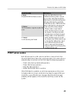
The drives in the computer you are servicing might have been 
rearranged or the drive startup sequence changed. Be extremely 
careful during write operations such as copying, saving, or 
formatting. Data or programs can be overwritten if you select an 
incorrect drive.

Attention

General error messages appear if a problem or conflict is found by an 
application program, the operating system, or both. For an explanation 
of these messages, refer to the information supplied with that software 
package.

Notes

•  The default is for this computer to boot up in quiet mode (no beep, 

no memory count and checkpoint code display) when no errors are 
detected by POST. 

•  To enable beep, memory count, and checkpoint code display when 

a successful POST occurs, do the following:
1. Start the Setup Utility program. See 

“Starting the Setup Utility 

program”

2. Select 

Start Options

3. Set 

Power-On Self-Test to Enhanced

.

•  Before replacing any FRUs, ensure that the latest level of BIOS is 

installed on the system. A down-level BIOS might cause false errors 
and unnecessary replacement of the system board.

Use the following procedure to help determine the cause of the problem: 
1.  Power-off the computer and all external devices. 
2.  Check all cables and power cords. 
3.  Set all display controls to the middle position. 
4.  Power-on all external devices. 

Summary of Contents for 3000 C Series

Page 1: ...spection guide 7 Handling electrostatic discharge sensitive devices 8 Grounding requirements 8 Safety notices 9 Chapter 3 General information 12 Specifications 12 Chapter 4 General Checkout 13 Problem determination tips 14 Chapter 5 Using the Setup Utility 16 Starting the Setup Utility program 16 Viewing and changing settings 16 Using passwords 17 Using Device 19 Selecting a startup device 20 Exit...

Page 2: ...r 35 Replacing the power board 38 Replacing the speaker system 42 Replacing the hard disk drive 43 Replacing an optical drive 47 Replace the Inverter board 49 Replacing the system fan 51 Replacing the camera 53 Replacing the wireless card 54 Replacing the TV tuner card 55 Replacing the CPU heat sink 57 Replacing the system board 59 Replacing the keyboard and mouse 61 Replacing the Mouse 62 Replaci...

Page 3: ... invalid for those machines which do not have TV card Important Safety Information Be sure to read all caution and danger statements in this book before performing any of the instructions Veuillez lire toutes les consignes de type DANGER et ATTENTION du présent document avant d exécuter les instructions Lesen Sie unbedingt alle Hinweise vom Typ ACHTUNG oder VORSICHT in dieser Dokumentation bevor S...

Page 4: ...com 2 Type the machine type Example 8129 in the Use Quick Path field then click Go 3 Under Browse by product click Continue 4 Under Important information click Parts information 5 In the Refine results field select Service parts then click the entry for your machine type The list of service parts by description with applicable machine type model and FRU part number is displayed Important informati...

Page 5: ... be used Products marketed before June 2006 Products marketed after June 2006 Current or original part Replacement FRU Current or original part Replacement FRU Non RoHS Can be Non RoHS Must be RoHS Must be RoHS Non RoHS Can be RoHS Non RoHS Can sub to RoHS RoHS Must be RoHS Note A direct substitution is a part with a different FRU part number that is automatically shipped by the distribution cente...

Page 6: ... you think are too heavy for you Do not perform any action that causes hazards to the customer or that makes the equipment unsafe Before you start the machine ensure that other service representatives and the customer s personnel are not in a hazardous position Place removed covers and other parts in a safe place away from all personnel while you are servicing the machine Keep your tool case away ...

Page 7: ... electrical equipment Important Use only approved tools and test equipment Some hand tools have handles covered with a soft material that does not insulate you when working with live electrical currents Many customers have near their equipment rubber floor mats that contain small conductive fibers to decrease electrostatic discharges Do not use this type of mat to protect yourself from electrical ...

Page 8: ... instructions are in the safety sections of maintenance information Use extreme care when measuring high voltages Regularly inspect and maintain your electrical hand tools for safe operational condition Do not use worn or broken tools and testers Never assume that power has been disconnected from a circuit First check that it has been powered off Always look carefully for possible hazards in your ...

Page 9: ...ed CRT face or bulging capacitor Mechanical hazards such as loose or missing hardware The guide consists of a series of steps presented in a checklist Begin the checks with the power off and the power cord disconnected Checklist 1 Check exterior covers for damage loose broken or sharp edges 2 Power off the computer Disconnect the power cord 3 Check the power cord for a A third wire ground connecto...

Page 10: ...static on your body Prevent the part from touching your clothing Most clothing is insulative and retains a charge even when you are wearing a wrist strap Use the black side of a grounded work mat to provide a static free work surface The mat is especially useful when handling ESD sensitive devices Select a grounding system such as those listed below to provide protection that meets the specific se...

Page 11: ... hand only to connect or disconnect signal cables Never turn on any equipment when there is evidence of fire water or structural damage Disconnect the attached power cords telecommunications systems networks and modems before you open the device covers unless instructed otherwise in the installation and configuration procedures Connect and disconnect cables as described in the following table when...

Page 12: ...by local ordinances or regulations CAUTION When laser products such as CD ROMs DVD ROM drives fiber optic devices or transmitters are installed note the following Do not remove the covers Removing the covers of the laser product could result in exposure to hazardous laser radiation There are no serviceable parts inside the device Use of controls or adjustments or performance of procedures other th...

Page 13: ...he power supply do not turn off the electrical current supplied to the device The device also might have more than one power cord To remove all electrical current from the device ensure that all power cords are disconnected from the power source 1 2 CAUTION Do not place any object weighing more than 82 kg 180 lbs on top of rack mounted devices ...

Page 14: ...ion Specifications This section lists the physical specifications for your computer Type Lenovo 3000 C This section lists the physical specifications Environment Air temperature Operating 10 to 35 C Transit 20 to 55 C Humidity Operating 35 to 80 Transit 20 to 93 40 C Altitude 86KPa to 106KPa Electrical input Input voltage 220V 22V Input frequency 50Hz 1Hz ...

Page 15: ...uter to boot up in quiet mode no beep no memory count and checkpoint code display when no errors are detected by POST To enable beep memory count and checkpoint code display when a successful POST occurs do the following 1 Start the Setup Utility program See Starting the Setup Utility program 2 Select Start Options 3 Set Power On Self Test to Enhanced Before replacing any FRUs ensure that the late...

Page 16: ...on available when requesting assistance from Service Support and Engineering functions Machine type and model Processor or hard disk upgrades Failure symptom Do diagnostics indicate a failure What when where single or multiple systems Is the failure repeatable Has this configuration ever worked If it has been working what changes were made prior to it failing Is this the original reported failure ...

Page 17: ...Chapter 4 General Checkout 15 Comparing the configuration and software set up between working and non working systems will often lead to problem resolution ...

Page 18: ... you hear multiple beeps release the F1 key Notes a If you are using a USB keyboard and the Setup Utility program does not display using this method repeatedly press and release the F1 key rather than leaving it pressed when turning on the computer b If a Power On Password or an administrator password has been set the Setup Utility program menu is not displayed until you type your password For mor...

Page 19: ...here to the following rules Must have at least seven characters in length Contain at least one alphabetic character and one numeric character Setup Utility program and hard disk drive passwords are not case sensitive Not be your name or your user name Not be a common word or a common name Be significantly different from your previous password Administrator password When a Administrator Password is...

Page 20: ...trator password do the following Note When prompted for a password you must type your Administrator password 1 From Security menu select Set Administrator Password and press Enter 2 The password dialog box will be displayed Enter Current Password and press Enter Press Enter in New Password and confirm New Password dialog A setup notice will display that changes have been saved 3 Press Enter to con...

Page 21: ...at changes have been saved 3 Press Enter to continue Using Device USB Setup When this feature is set to Disable the device of USB Setup is disabled and will not be displayed in the system configuration To set Device do the following 1 Start the Setup Utility program see Starting the Setup Utility program on page 16 2 From the Setup Utility program menu select Devices 3 Select USB Setup 4 Select Di...

Page 22: ... when turning on the computer 3 Select the desired startup device from the Startup Device Menu and press Enter to begin Note Selecting a startup device from the Startup Device menu does not permanently change the startup sequence Selecting or changing the startup device sequence To view or permanently change the configured startup device sequence do the following 1 Start the Setup Utility program ...

Page 23: ...rogram When you finish viewing or changing settings press Esc to return to the Setup Utility program menu you might have to press Esc several times If you want to save the new settings select Save changes and Exit before you exit Otherwise your changes will not be saved ...

Page 24: ...iagnose the error message first If you cannot run the diagnostic tests or you get a diagnostic error code when running a test but did receive a POST error message diagnose the POST error message first If you did not receive any error message look for a description of your error symptoms in the first part of this index Hard disk drive boot error A hard disk drive boot error error codes 1962 and I99...

Page 25: ...k drive The drive is defective Replace the hard disk drive Power Supply Problems If you suspect a power problem use the following procedures Check Verify FRU Action Check the following for proper installation Power Cord On Off Switch connector On Off Switch Power Supply connector System Board Power Supply connectors Microprocessor s connection Reseat connectors Check the power cord for continuity ...

Page 26: ...malfunctioning add in card Remove all expansion cards except the video adapter If beep codes are generated when all other expansion cards are absent consult your system manufacturer s technical support If beep codes are not generated when all other expansion cards are absent one of the add in cards is causing the malfunction Insert the cards back into the system one at a time until the problem hap...

Page 27: ...o the system one at a time until the problem happens again This will reveal the malfunctioning card 10 beeps CMOS shutdown register read write error 11 beeps Cache memory test failed POST error codes Each time you power on the system it performs a series of tests that check the operation of the system and some options This series of tests is called the Power On Self Test or POST POST does the foll...

Page 28: ...nstalled Primary Slave Hard Disk Error Secondary Master Hard Disk Error Secondary Slave Hard Disk Error PS2 Mouse not found PS2 Mouse support is enabled in the BIOS setup butthe device is not detected You can plug PS2 Mouse or set PS2 Mouse support is auto Keyboard error Cannot initialize the keyboard Make sure the keyboard is properly connected to the computer and that no keys are held pressed du...

Page 29: ...ure that the hard disk drive is jumpered as a master and the optical drive is jumpered as a slave 1 Power off the computer 2 Remove or disconnect the following components if installed one at a time a External devices modem printer or mouse b Any adapters c Memory modules d Extended video memory e External Cache f External Cache RAM g Hard disk drive h Diskette drive 3 Power on the computer to re t...

Page 30: ...ng the computer cover Locating components and connectors The following illustrations will help you to locate the various components and connectors in your computer Internal components The following illustration shows the components inside your computer Front bezel LCD Inverter Speaker ODD ODD cable Rear cover Heat Sink HDD CPU fan Camera Power board RAM WLAN TV CARD Power cable Camera cable HDD ca...

Page 31: ...devices that are factory installed or that you can install later The following illustration shows the locations of parts on the system board Front view of the system board 1 2 3 4 5 6 7 8 9 1 LCD panel power cable connector 2 System fan cable connector 3 Camera cable connector 4 Inverter board cable connector 5 HDD fan cable connector 6 WLAN card connector 7 Power board connector 8 TV tuner module...

Page 32: ...ts 3 Memory card reader 4 IEEE 1394 connector 5 Headphone connector 6 Microphone connector 7 USB connectors 2 8 USB connectors 4 9 Ethernet connector q PS2 Keyboard connector qa TV tuner Select models only qs Power connector qd HDD power cable connector qf HDD SATA 2 connector qg ODD SATA 1 connector qh ODD power cable connector ...

Page 33: ...nual HMM for the computer To obtain copies of the Safety and Warranty Guide or HMM go to the Support Web site at http consumersupport lenvov com Note Use only parts provided by Lenovo General information Pre disassembly instructions Before proceeding with the disassembly procedure make sure that you do the following 1 Turn off the power to the system and all peripherals 2 Unplug all power and sign...

Page 34: ...loth to protect the touch screen surface from scratches or other damage 1 Remove any media diskettes CDs or memory cards from the drives shut down your operating system turn off all attached devices and the computer 2 Unplug all power cords from electrical outlets 3 Disconnect all cables attached to the computer This includes power cords input output I O cables and any other cables that are connec...

Page 35: ...he side of the computer and then remove it 6 Push out the latches on both sides of the memory socket to release the memory module 1 and gently pull the memory module upward to remove it from its socket 2 Both memory modules can be removed by using the same procedure ...

Page 36: ...ardware Maintenance Manual 34 1 1 2 7 Align then insert the new memory module into the socket 1 and push down on the top edge of the memory module 2 Make sure the latches lock the memory module in place ...

Page 37: ...de the memory cover backward until it snaps into position 9 Screw back the screw on the memory cover Removing the computer cover Attention Turn off the computer and wait 3 to 5 minutes to let the computer cool before removing the computer cover ...

Page 38: ...amage 1 Remove any media diskettes CDs or memory cards from the drives shut down your operating system turn off all attached devices and the computer 2 Unplug all power cords from electrical outlets 3 Disconnect all cables attached to the computer This includes power cords input output I O cables and any other cables that are connected to the computer Refer to Locating connectors on the rear of th...

Page 39: ...he computer upside down on the flat surface Release the left and right tabs from the connector housing then pull each side of the cover out slightly 1 release the top tabs from the connector housing then lift the cover away from the computer 2 ...

Page 40: ...place the power board 1 Remove the computer cover Refer to Removing the computer cover 2 Place the computer cover upside down on a flat surface 3 Disconnect the cable from the power board 1 4 Remove the two screws that hold the power board to the computer cover 2 ...

Page 41: ...d 6 Align the screw holes on the power board to the mounting holes on the computer cover 7 Screw back the two screws on the new power board 8 Connect the power board cable to the power board 9 Install the computer cover Refer to Completing the installation ...

Page 42: ... LCD panel To replace the LCD panel 1 Remove the computer cover Refer to Removing the computer cover 2 Remove four screws that hold the LCD panel to the chassis 3 Disconnect the LCD panel three cables from the system board 1 and inverter board 2 ...

Page 43: ...Chapter 7 Replacing hardware 41 4 Carefully detach the LCD panel from the chassis ...

Page 44: ...l is dirty 6 Screw back the four screws on the LCD panel 7 Install the computer cover Refer to Completing the installation Replacing the speaker system To replace the left and right speakers 1 Remove the computer cover Refer to Removing the computer cover 2 Remove the LCD panel Refer to steps 2 to 4 of the Replacing the LCD panel section 3 Remove the four screws that secure the left and right spea...

Page 45: ...akers to the chassis 6 Install the LCD panel Refer to steps 5 to 6 of the Replacing the LCD panel section 7 Install the computer cover Refer to Completing the installation Replacing the hard disk drive To replace the hard disk drive 1 Remove the computer cover Refer to Removing the computer cover 2 Remove the LCD panel Refer to steps 2 to 4 of the Replacing the LCD panel section ...

Page 46: ...Hardware Maintenance Manual 44 3 Disconnect the data and power cables from the hard disk drive 4 Remove the screw that secures the hard disk drive to the chassis ...

Page 47: ...Chapter 7 Replacing hardware 45 5 Pull out the hard disk drive from the chassis 6 Remove the four screws that secure the hard disk drive to the drive bay ...

Page 48: ...rive into the drive bay 2 Screw back the four screws on the drive bay 9 Screw back the hard disk drive bay back to the chassis 10 Connect the data and power cables back to the hard disk drive 11 Install the LCD panel Refer to steps 5 to 6 of the Replacing the LCD panel section 12 Install the computer cover Refer to Completing the installation ...

Page 49: ...e the computer cover Refer to Removing the computer cover 2 Remove the LCD panel Refer to steps 2 to 4 of the Replacing the LCD panel section 3 Remove the screw that secures the optical drive to the chassis 4 Disconnect one end of the ODD data and power cables from the rear of the optical drive ...

Page 50: ...Hardware Maintenance Manual 48 5 Slide the optical drive out of the drive bay 6 Remove the two screws that secure the optical drive to the metal bracket ...

Page 51: ... the ODD data and power cables to the optical drive 10 Install the LCD panel Refer to steps 5 to 6 of the Replacing the LCD panel section 11 Install the computer cover Refer to Completing the installation Replace the Inverter board To replace the inverter board 1 Remove the computer cover Refer to Removing the computer cover 2 Remove the LCD panel Refer to steps 2 to 4 of the Replacing the LCD ...

Page 52: ...cal drive Refer to the steps 3 to 5 of the Replacing the optical drive section 4 Disconnect the inverter board cable from the inverter board 1 and remove the two screws that secure the inverter board to the chassis 2 5 Pull the inverter board away from the chassis ...

Page 53: ...ection 10 Install the LCD panel Refer to steps 5 to 6 of the Replacing the LCD panel section 11 Install the computer cover Refer to Completing the installation Replacing the system fan To replace the system fan 1 Remove the computer cover Refer to Removing the computer cover 2 Remove the LCD panel Refer to steps 2 to 4 of the Replacing the LCD panel section 3 Remove the four screws that secure the...

Page 54: ...5 Align the four screw holes on the new system fan to the four mounting holes on the chassis 6 Insert and tighten the four screws to secure the system fan 7 Connect the system fan cable to the system board 8 Install the LCD panel Refer to steps 5 to 6 of the Replacing the LCD ...

Page 55: ...e computer cover Refer to Removing the computer cover 2 Remove the LCD panel Refer to steps 2 to 4 of the Replacing the LCD panel section 3 Remove the two screws that secure the camera to the chassis 1 and disconnect one end of the camera cable from the rear of the camera and the other end of the cable from the system board 2 4 Pull the camera away from the chassis ...

Page 56: ... section 8 Install the computer cover Refer to Completing the installation Replacing the wireless card To replace the wireless card 1 Remove the computer cover Refer to Removing the computer cover 2 Remove the LCD panel Refer to steps 2 to 4 of the Replacing the LCD panel section 3 Disconnect the two antenna cables from the wireless card 1 4 Remove the two screws that secure the wireless card to t...

Page 57: ...rew back the two screws on the wireless card 8 Connect the two antenna cables to the wireless card 9 Install the LCD panel Refer to steps 5 to 6 of the Replacing the LCD panel section 10 Install the computer cover Refer to Completing the installation Replacing the TV tuner card To replace the system board 1 Remove the computer cover Refer to Removing the computer cover ...

Page 58: ...TV tuner card to the system board 2 5 Detach the TV tuner card from the TV tuner card connector 6 Align then insert the new TV tuner card to the TV tuner connector 7 Screw back the two screws on the TV tuner card 8 Connect the antenna cable to the TV tuner card 9 Install the LCD panel Refer to steps 5 to 6 of the Replacing the LCD panel section 10 Install the computer cover Refer to Completing the...

Page 59: ...er cover 2 Remove the LCD panel Refer to steps 2 to 4 of the Replacing the LCD panel section 3 Disconnect all the cables from the upside of the system board 4 Remove the eight screws that secure the system board to the chassis 5 Pull the system board away from the chassis and disconnect all the cables away from the underside of the system board ...

Page 60: ...dware Maintenance Manual 58 6 Place the system board upside down on a flat surface 7 Loosen the seven screws that secure the CPU heat sink to the chassis 6 1 4 2 3 7 5 8 Pull out the heat sink from the CPU ...

Page 61: ...ck the eight screws on the system board 15 Connect related cables to the upside of the system board 16 Install the LCD panel Refer to steps 5 to 6 of the Replacing the LCD panel section 17 Install the computer cover Refer to Completing the installation Replacing the system board To replace the system board 1 Remove the computer cover Refer to Removing the computer cover 2 Remove the LCD panel Refe...

Page 62: ...ct all the cables from the upside of the system board 6 Remove the eight screws that secure the system board to the chassis 7 Pull the system board away from the chassis and disconnect all the cables away from the underside of the system board ...

Page 63: ...ard on the upside of the new system board Refer to the step 6 to 8 of the Replacing the TV tuner card section 17 Install the wireless card on the upside of the new system board Refer to the step 6 to 8 of the Replacing the wireless card section 18 Connect related cables to the upside of the system board 19 Install the LCD panel Refer to steps 5 to 6 of the Replacing the LCD panel section 20 Instal...

Page 64: ...and connect the new keyboard cable to the same connector Replacing the Mouse Attention Do not remove the computer cover or attempt any repair before reading the Important safety information in the Safety and Warranty Guide that was included with your computer or in the Hardware Maintenance Manual HMM for the computer To obtain copies of the Safety and Warranty Guide or HMM go to the Support Web si...

Page 65: ...r Replacing the power cord or power adapter Attention Do not remove the computer cover or attempt any repair before reading the Important safety information in the Safety and Warranty Guide that was included with your computer or in the Hardware Maintenance Manual HMM for the computer To obtain copies of the Safety and Warranty Guide or HMM go to the Support Web site at http consumersupport lenovo...

Page 66: ...bles including wired internet and power cords Also depending on the parts replaced you might need to confirm the updated information in the Setup Utility program Refer to Starting the Setup Utility in the User Guide or in the Hardware Maintenance Manual 1 Ensure that all components have been reassembled correctly and that no tools or loose screws are left inside your computer Refer to Locating com...

Page 67: ...nges sides of the computer chassis 3 Position the computer cover on the chassis so that the tabs on the cover align with the slots of the chassis 4 Carefully install the cover as shown until it securely snaps into place 5 Install and tighten the six screws on the chassis ...

Page 68: ... cables and power cords into the computer Refer to Locating components and connectors Note In most areas of the world Lenovo requires the return of the defective CRU Information about this will come with the CRU or will come a few days after the CRU arrives ...

Page 69: ...stems support ACPI BIOS mode Automatic Power On features The Automatic Power On features within the Power Management menu allow you to enable and disable features that turn on the computer automatically Wake on LAN If the computer has a properly configured token ring or Ethernet LAN adapter card that is Wake on LAN enabled and there is remote network management software you can use the Wake on LAN...

Page 70: ...escribed in all the manuals included with your computer and the content of the manual at any time without additional notice All the manuals included with your computer is provided to help you use Lenovo products appropriately but it does not represent any description of the software hardware configuration for the product For the configuration of the product refer to related contract if any product...

Page 71: ...deon The Ultimate Visual Experience and combinations thereof are trademarks of Advanced Micro Devices Inc in the United Sates and or other jurisdictions This is description of trademarks or registered trademarks of Lenovo and its partners Other registered trademarks mentioned in all the manuals included with your computer belong to the specific company respectively All rights reserved All the manu...

Reviews: