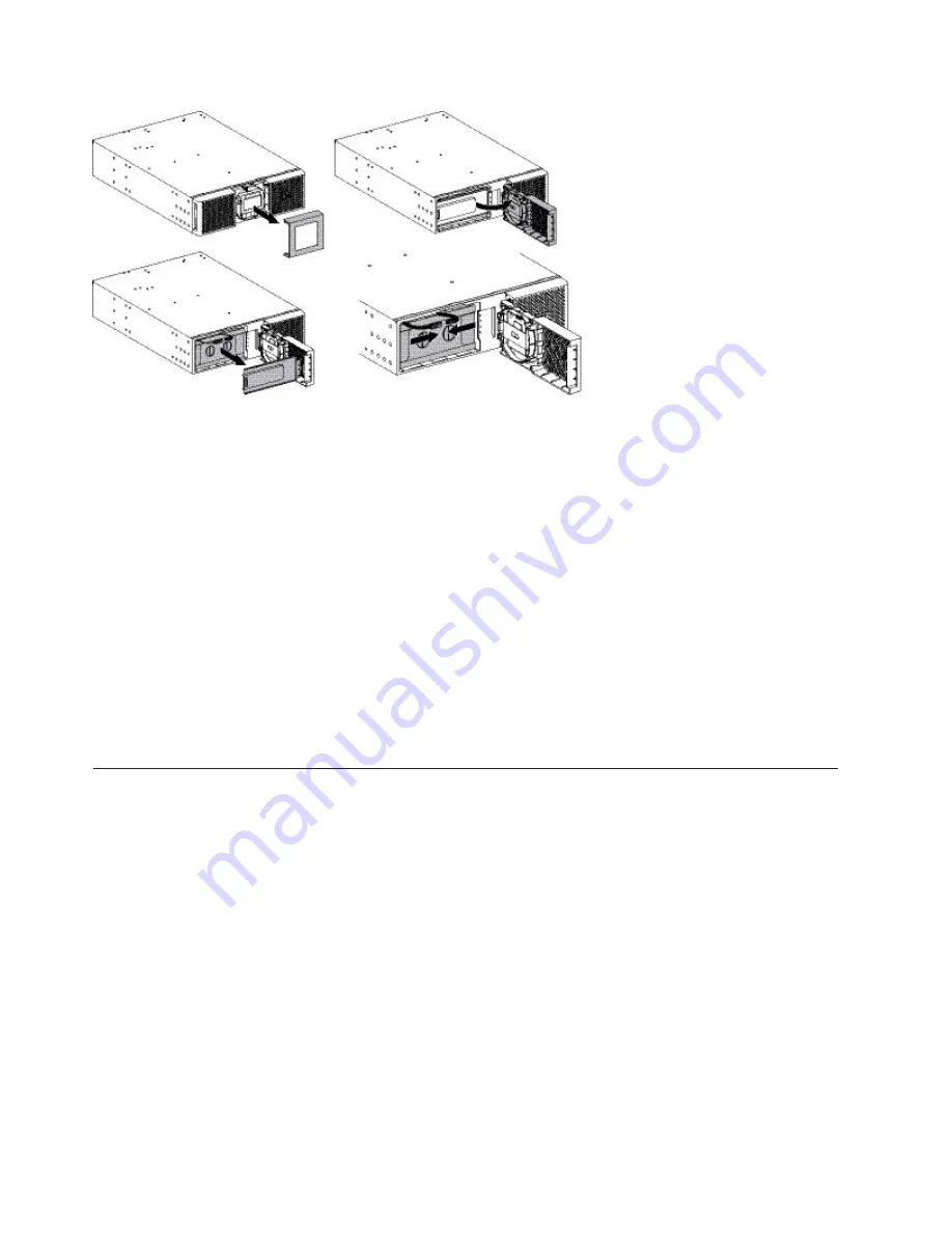
To install the UPS:
Procedure
1.
Remove the center cover of the front bezel.
2.
Loosen the two screws to open the left side of the front bezel.
3.
Remove the two screws to pull out the metal protection cover of the battery
pack.
Note:
A ribbon cable connects the LCD control panel to the UPS. Do not pull
on the cable or disconnect it.
Note:
A small amount of arcing might occur when connecting the battery pack.
This is normal and does not damage the UPS or present any safety concern.
4.
Connect the two battery-pack connectors together.
5.
Screw back the metal protection cover and the front bezel, then clip the center
cover.
Connecting the EBM(s)
About this task
Note:
A small amount of arcing might occur when connecting EBMs. This is
normal and will not harm personnel. Insert the EBM cable into the battery
connector quickly and firmly.
Procedure
1.
Plug the EBM power cable(s) into the battery connector(s). Up to four EBMs
can be connected to the UPS.
2.
Verify that the EBM connections are tight and that strain relief exists for each
cable.
3.
Connect the battery detection cable(s) to the connector of the UPS and of the
EBM(s).
20
Installation and User's Guide
Summary of Contents for 5594-5KX
Page 1: ...3U Rack or Tower UPS RT5 0kVA and RT6 0kVA Installation and User s Guide ...
Page 2: ......
Page 3: ...3U Rack or Tower UPS RT5 0kVA and RT6 0kVA Installation and User s Guide ...
Page 6: ...iv Installation and User s Guide ...
Page 18: ...xvi Installation and User s Guide ...
Page 22: ...4 Installation and User s Guide ...
Page 34: ...16 Installation and User s Guide ...
Page 50: ...32 Installation and User s Guide ...
Page 60: ...42 Installation and User s Guide ...
Page 72: ...54 Installation and User s Guide ...
Page 84: ...66 Installation and User s Guide ...
Page 86: ...68 Installation and User s Guide ...
Page 87: ......
Page 88: ...Part Number 00WA360 Printed in USA 1P P N 00WA360 ...


