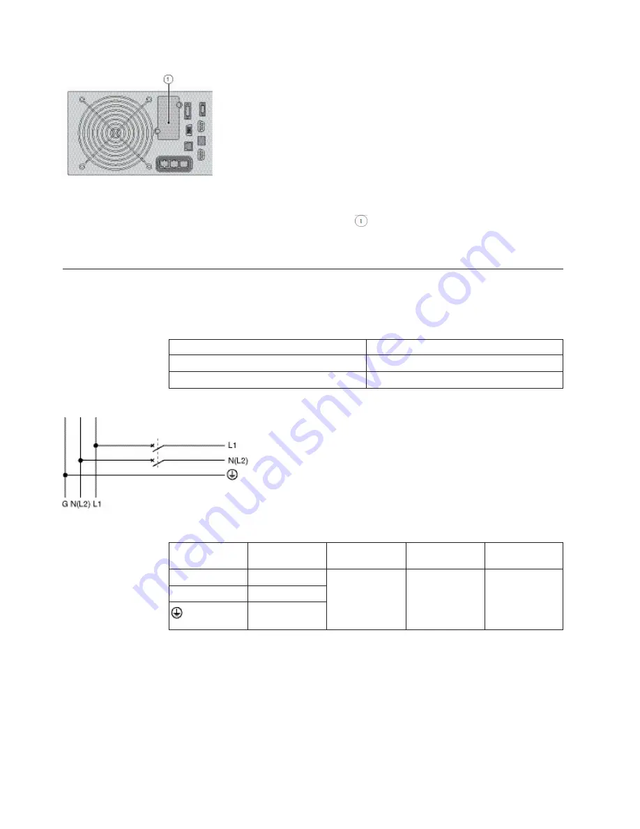
Procedure
1.
Remove the connector panel blank (
), which is secured by two screws.
2.
Insert the UPS Network Management Card into the slot. Secure the panel by
tightening the two screws.
Installation requirements
Recommended protective devices and cable cross-sections
1.
Recommended upstream protection
UPS power rating
Upstream circuit breaker
5000VA
D curve – 30A
6000VA
D curve – 30A
2.
Recommended cable cross-sections
Terminal
position
Wire function
Terminal wire
size rating
Minimum input
wire size
Tightening
torque
L1
Phase
4-16 mm
2
(12-6
AWG)
6 mm
2
(10 AWG)
105°C
10 mm
2
(8 AWG)
75°C
10 lb in / 1.13
Nm
N(L2)
Neutral
Ground
Copper wire, solid or stranded.
24
Installation and User's Guide
Summary of Contents for 5594-5KX
Page 1: ...3U Rack or Tower UPS RT5 0kVA and RT6 0kVA Installation and User s Guide ...
Page 2: ......
Page 3: ...3U Rack or Tower UPS RT5 0kVA and RT6 0kVA Installation and User s Guide ...
Page 6: ...iv Installation and User s Guide ...
Page 18: ...xvi Installation and User s Guide ...
Page 22: ...4 Installation and User s Guide ...
Page 34: ...16 Installation and User s Guide ...
Page 50: ...32 Installation and User s Guide ...
Page 60: ...42 Installation and User s Guide ...
Page 72: ...54 Installation and User s Guide ...
Page 84: ...66 Installation and User s Guide ...
Page 86: ...68 Installation and User s Guide ...
Page 87: ......
Page 88: ...Part Number 00WA360 Printed in USA 1P P N 00WA360 ...


